The Software Engineering Problem
How to bridge the gap between customer requirements and code. In some domains, this gap is huge, because requirements are stated in terms of waffly things like goals and needs - not functionality. The traditional answer is that "a miracle occurs", or that it's ad-hoc, and "gurus" are needed. As a result, the process is unpredictable and costly. Can we provide a systematic approach to bridge the gap?
Planning is essential. It happens in other engineering disciplines, and plans are required, because massive changes are costly. Although it is vital to plan, even the best plans can go wrong, so plans can be written to be changed, and anticipating change is a modern software engineering reality. Planning is especially critical in large systems, however large is not necessarily complex.
Adopting a development methodology is one approach to solving this problem. These methodologies provide a process which consists of steps and phases which, if followed, may make it easier to bridge the gap. There are lots of methodologies, but this course focuses on elements of object orrientation (specifically, UML and RUP).
Object Orrientation
Object orrientation is often what is applied in industry (the critical industry is more conservative, but even they are interested in things such as Safe-C++). OO can enable engineering of more maintainable and extensible systems and helps in building reusable components and therefore large-scale systems.
However, it must be born in mind that it is not always the best approach to take - following any methodology blindly can cause problems), but it is helpful in the right setting.
OO development is the use of classes and systems in developing software and systems. Classes represent recurring, reusable, extensible concepts that provide services - similar to types. Objects are instances of classes and carry out computation in response to messages. OO development implies using classes and objects throughout the construction process, for all parts, including requirements analysis, design, coding and testing.
Typical Development Processes
The waterfall, spiral and V-models all have the following phases, in some kind of order:
- Requirements analysis
- Specification and design
- Implementation
- Testing
- Delivery
- Maintenance
Waterfall Process
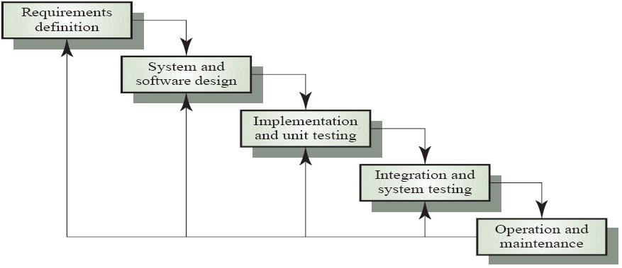
This method was first proposed by Royce in 1970. Each stage must be signed off and can be repeated or feedback to an earlier stage. It's not an accurate model any longer - it was in the 1970s, however it was developed for small, simple programs. Modern methods have become refined and improved.
Spiral Process
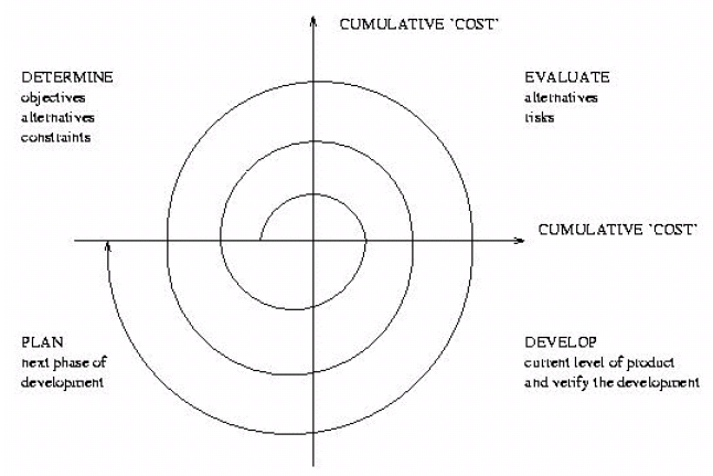
Created by Barry Boehm, the spiral process incourages incremental development and makes the risks and costs of both resources and failure explicit in the process.
Rational Unified Process
Also known as just RUP, this is a "use case and architecture-driven process" from IBM Rational. Based on a "reasonable" set of user stories, developers go through a suite of iterations, refining the stories to OO design. In each iteration, additional information is added to the designs. Again, this is an incremental approach to development.
RUP also specifies a management process that can help to monitor and measure progress.
User Stories
Written from a users perspective, using their vocabulary - often there is no mention of computer systems, software or user interfaces. Some things can be imprecise or unstated, stories are often broken up into normal cases and exceptional cases. Use cases are a way to write stories.
Model Driven Development
RUP is a special case of a more general category - model driven development, or MDD. The aim with MDD is to build software using blueprints - things that are at a higher level of abstraction than code (e.g., Ada packages, Java classes, etc). From this we get a model of the system, however a model is not necessarily a diagram.
In this module, we'll look at one type of blueprinting language - UML, although many other exists, in addition to other MDD processes.
MDD is essentially expanding the waterfall methods and the development quadrent of the spiral method. MDD has a basis in formal methods, where each level of abstraction has to be verifiably consistent with each other.
The Object Management Group (a consortium of interested platforms, originally interested in OO programming, which now produces standards) has created the model driven architecture, a standardised approach to the MDD. In the MDA, you start with a PIM (platform independent model) which must then be converted into a PSM (platform specific model). With the PSM, automated code generation codes can be used to generate the running code. This code is often inelegant and hard to maintain by hand.
We can look at the MDA in more detail on the diagram below:
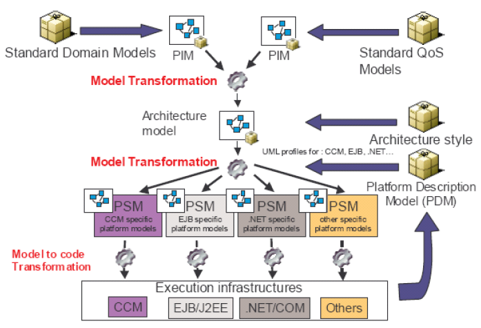
This diagram adds the PDM, a model of the platform which is used for the code generation. In theory, this can be used to generate a PSM from the PIM.
Extreme Programming
Extreme Programming (or XP) is a view of interest in industry and research. Here, code is the most important deliverable and everything else is much less and may be ignored.
Development starts with coding, and changes to your design or requirements are reflected immediately in code. There are questions whether or not this is sensible, or even dangerous and if it is compatible with modelling or not.
XP takes the best bits of hacking and adds things such as peer review to generate an efficient method of development
Agile Methods
XP is an instance of the so called Agile methodology. These methodologies emphasise incremental development and deprecate the production of non-code output, as the customer presumably wants code. Agile methods do not say "Don't write documentation" - they say write only what will help.
The principles of agile development are:
- Early and continuous development of valuable software
- Welcome changing requirements, and harness them for competitive advantage
- Deliver working software frequently
- Business people and developers working together on a day-to-day basis
- A continuous attention to technical detail
- Simplicity is essential
- Self-organising teams that reorganise and assess progress regularly
Software Quality
The principle goal of software engineering is to produce quality software. There are both internal and external factors that influence software quality.
Internal factors are perceptable to computer professionals (e.g., efficiency of algorithms and data structures). The customer doesn't care about these directly, but they are how we satisfy the requirements.
External factors are preceived by the client, and are clearly the most important. Some example of external quality factors are:
- Correctness - ability of the software to be able to perform tasks defined by its specifications
- Robustness - ability of the software to react appropriately to abnormal conditions
- Extendibility - the ease of adapting software to changes in the specifications
- Reusability - the ability of different software to serve for the construction of many different systems
- Efficiency - places minimal demands as possible on hardware resources
- Portability - ease of transferring software to different environments
- Ease of use
- Timeliness - ability to get the software out of the door when the client wants it
High quality OO systems will be non-monolithic, i.e., will be divided up into classes, each of which provide a distinct set of services. These classes will be:
- understandable - to determine what a class does, you should need to understand as little of the class's context as possible - this is subjective, however
- continuous - if you modify a class, a minimum number of other classes will have to change
- protected - classes avoid propagating error conditions to neighbouring classes
There are five rules to help build high quality OO systems, and our programming and modelling languages must provide support for these rules.
Direct Mapping Rule
The class structure devised in the process of building a software system should remain compatible with any class structure devised in the process of modelling the problem domain.
To address the needs of the clients, their problem must be understood, and then a solution formulated. Developers may model the customers needs and the solution in a language (e.g., UML). A seamless mapping is needed from the solution in UML through to a software implementation. Seamlessness involves using a common set of concepts throughout development (classes and objects).
In practice, this isn't quite enough, however. It's difficult to describe customer requirements in terms such as objects and classes. Requirements are often goal/event/need-based, and are more easily expressed in non-class forms, so the seamless process is extended with techniques such as use cases and interactions.
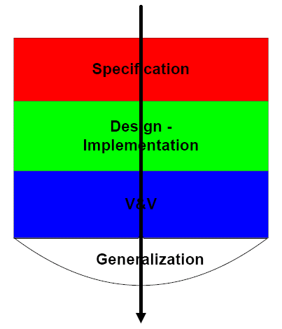
(Specification, Design, Implementation, Validation and verification, Generallisation)
Reversability (as demonstrated in the above diagram) is like the backwards arrows in the waterfall model, and is often required - for example to allow automatic construction of UML models from code and the automatic generation of meaningful demonstration.
Few Interfaces Rule
Every class should communicate with as few others as possible.
Thus, restrict the number of communication channels between classes (e.g., the number of services that can be invoked). This can improve understanding and protection.
Small Interfaces Rule
If two classes communicate, they should exchange as little information as possible.
This is also known as weak coupling, and relates to the size of connections, as opposed to their number.
Explicit Interfaces Rule
Whenever two classes, A and B communicate, this must be obvious from the text of A or B, or both.
Previous rules have established that communication should be limited to a few participants, and then only a few words. This rule requires that communication be loud and public. This is very important with respect to understanding.
Communication here refers to both messages between objects and the sharing of data.
Information Hiding Rule
The designer of every class must select a subset of services as the official information about the class, to be made available to the authors of the client classes. (David Lorge Parnas)
Only some, but probably not all, of the class's services are public. The rest are secret. The public part is the class's interface.
Software Construction Principles
The following principles apply to any kind of component, not just classes.
- Lingusitic units - components must correspond to syntactic language units
- Self-documentation - component designers should make all of its information part of the component itself
- Uniform access - all component services must be available through a uniform notation
- Single choice - whenever a component must support a set of alternatives, one and only one component in the system should know the exhaustive list
- Open-closed - services can be added (open), but the interface is stable for the clients to use (closed). Both of these are needed in real projects. The classic approach is to close when we reach stability, reopening when needed. But for this, we will need to reopen all the clients too. This is clearly undesirable.
Modelling
At each phase in the MDD process, we create models - an abstract representation of reality. For MSD, these are diagrams, but this is not necessarily the case. Models capture the essence of things of interest - during requirements analysis we model the essence of customer goals and needs, and during design we model the essence of the systems that will satisfy the requirements. We use models as they are usually easier to change than the system itself.
OO Modelling vs. OO Programming
OO modelling involves abstraction and planning. No code is written in the modelling stage; the essentials of a system are planned out and written down, often in a graphical notation (e.g., UML).
OO programming involves expressing an OO model in an executable language.
The Unified Modelling Language (UML)
The UML is a visual language for describing systems, and is a successor to the wealth of OO analysis and design methods of the 80s and 90s. It's mainly based on the work of Booch, Rumbaugh (OMT) and Jacobson. The OMG standard for UML is currently 2.0, but many organisations still using 1.x, and not all tools fully support 2.0 yet.
An important fact to remember is that the UML is only a language - it doesn't specify a development or management process, methods need a language and a process. UML is typically used with RUP, MDA or some other agile method. OMT, Objectory and Fusion are examples of other methods which include UML.
UML consists of two main parts:
- the graphical notation, used to draw models
- a metamodel which provides rules clarifying which models are valid and which are invalid
UML consists of a series of different diagrams, such as the:
- class diagrams, the essentials and advanced concepts
- interaction diagrams, for specifying object interactions and run-time behaviour via message passing (communication diagrams in UML 2.0)
- state charts, for specifying object behaviour and state changes (reactions to messages)
- use case diagrams, for capturing scenarios of system use
- physical diagrams, for mapping software elements to physical components
- extension mechanisms
- activity diagrams
Essentials of OO and UML 2.0
OO has static concepts:
- classes
- features of classes (attributes and operations)
- visibility
- relationships (client-supplier and inheritence)
- packages
And dynamic concepts:
- objects
- dynamic dispatch
- substitution
- messages
- events
We can also consider design-by-contract.
OO also considers use cases and actors. These ideas themselves aren't actually OO, but are used in concept with OO ideas. They can be helpful in finding classes and objects, but they can be dangerous and misleading.
There are also modelling extensions (e.g., stereotypes) and UML state machines (a simple extension of concepts seen in the first year).
Classes
The most important concept in OO is the class. A class is a module (consisting of a data part and an operation part) and a type (which can declare instances; objects), although there are many different definitions of this.
Each class has an interface and the interface declares and defines the services/features that the class provides. It also describes how to access these services; the interface could be considered to be the public face of these services. With interfaces, you don't need to consider what's happening internally.
All of OO analysis, design and programming revolves around the classes, which suggests the question - how do we find the classes?
A class is represented in UML as shown below (e.g., a stack)
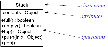
Sections on the class box can be hidden/elided as seen fit. There are also variants on this diagram too (stereotypes). Different UML tools also variously implement operation signatures (the way of defining operations).
Classes have features of two types, attributes (or fields) that are used to hold data associated with objects, and operations, used to implement behavior and computations. Attibutes can be as specific as you like (e.g., defining them as an integer type), and neither operations or data is compulsary in a class. Some tools do restrict the types you are allowed (e.g., Visio), but pure UML has no restrictions. Operations can exist in two forms, functions and procedures. Functions are operations that calculate and return a value (they do not change the state of an object, i.e., make persistent, visible changes to values stored in fields). Procedures are operations that change the state of an object (but do not return any values - however, they do support in/out values). Seperating functions from procedures in this way is useful in simplifying systems, for verification and testing.
An operation in UML specifies the services that a class can provide to its clients, and is implemented using a method. The full UML syntax for an operation is: visibility name(param_list) :type {constraint} . The constraint may include pre- and post- conditions (boolean expressions that determines whether or not an expression can be, or has been, evaluated). An operation should be considered as an interface implemented by one or more methods.
Visibility
Each feature of classes may be visible or invisible to other classes (clients). It is recommended (but not required) to not allow clients to write to/change fields directly. Each feature in a class can be tagged with visibility permissions (Java/UML).
- private (-) - the feature is inaccessible to clients and children
- public (+) - the feature is completely accesibly to clients
- protected (#) - the feature is inaccesible to clients (but accesible to children)
UML also allows you to define language-specific visibility tags.
OO programs are basically a series of feature calls, i.e., accesses to attributes and operation calls (recall the uniform access principle - implies that all feature calls are written using a single notation).
Objects
An OO program declares a number of variables (e.g., attributes, locals, and parameters) and each variable can refer to (or be attached to) an object. An object is a chunk of memory that may be attached to a variable which has a class for its type.
Using an object has two steps - declaration of a variable and allocation.
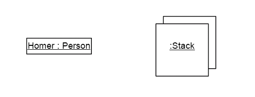
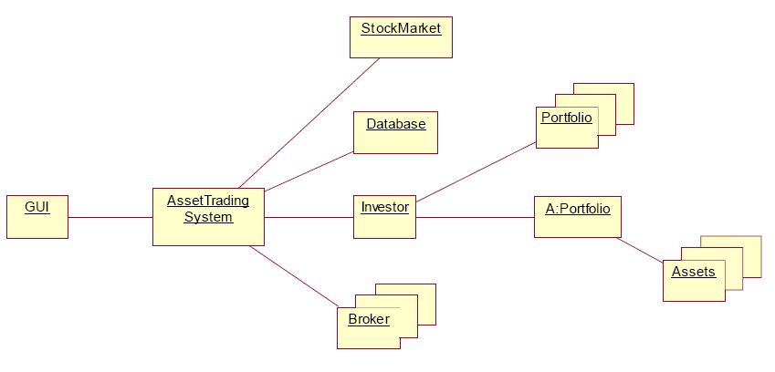
Each object optionally has a name (e.g., an object of type Person has the name Homer), and multiple instances of an object can be represented as on the right (useful for containers and in representing collaboration of objects). This however represents declaration and allocation, but not allocation by itself.
Constructors
A class should contain special features called constructors - this is invoked when an object is allocated and attached to a variable. Constructors in Java have the same name of the class, and there may be many of them (overloaded - for example, so it can be constructed using different sets of startup data).
Constructors are invoked on allocation. UML has the <<constructor>> stereotype.
Class Relationships
Individual classes are boring. Connecting them is what generates interesting emergent behaviour. Connecting them is also what could cause problems and generate errors, so we need to be careful and systematic when deciding how to connect classes.
In general, there are only two basic ways to connect a class:
- by client-supplier relationships
- by inheritence relationships
Both of these have speciallisations in UML, though.
Client-Supplier Relationships
One class may need to use another class (e.g., to create an object, call a feature, attach to, include, etc...). We say that the client uses services provided by a supplier. There are many different client-supplier relationships. There are specific kinds of relationships:
- Has-A - e.g., Board has-a collection of Squares
- Creates - e.g., Factory is responsible for creating instances of motors (example of a type of design pattern)
- Part-Of - a Cylinder is a part-of a Motor (no sharing of the constituent parts). Some programming languages support part-of relationships via composite, or expanded, types.
Associations represent relationships between instances of classes and are the basic way to represent client-supplier in UML. Each association has two association ends, and each association end can be named with a role. If there is no role, you name an end after a target class. Association ends can also have multiplicities.
Multiplicities are constraints that indicate the number of instances that participate in a relationship. The default multiplicity on a role is 0..*. Other multiplicities include:
- 1 - exactly one instance
- * - same as 0..*
- 1..* - at least one
- 0..1 - common participation
You can, in general, specify any number, contiguous sequence n..m, or set of number {0, 2, 4} on a role. Note: multiplicities constrain instances.
Responsibilities
An association implies some relationship for updating and maintaining the relationship. This is not shown on the diagram, so it can be implemented in several ways, such as a method. Responsibilities do not imply data structure. If you want to indicate which participant is responsible for maintaining the relationship, add navigability.
A navigable association indicates which participant is responsible for the relationship, e.g.,
![]()
Here, game is responsible for the relationship. In a model of a Java program, this may indicate that a Game object refers to (points to, or "has-a") a Room object.
The default, "undirected" association really means bidirectional! Directed associations are typically ready as "has-a" relationships.
Attributes and Associations
An attribute of a class represents state - information that must be recorded for each instance, but associations imply that one class can access all of another class, even if that is not what is wanted. At the implementation level, the difference between associations and attributes is normally very small, so attributes can be considered to be small, simple objects that do not have their own identity.
Inheritance
If we recall the open-closed principle, we need a mechanism for re-opening a class to change, add and remove features. Inheritance allows us to re-open a class once it is closed.
Inheritance is a relationship between a child class and one or more parent classes. The inheriting class (the child/subclass) inherits features from its parents, and may add its own.
In UML, we call inheritance generalisation. For example, if we have personal and corporate customers that have similarities and differences, we can place the similarities in a customer class and the difference in generalisations of customers, as shown below:
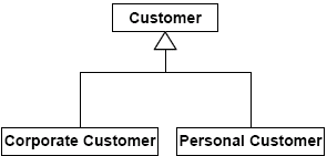
All the features of customer are features of its generalisations too. This implies substituability.
There are many different types of inheritance. Subtyping inheritance is used when there is a strong degree of commonality between two or more classes, e.g., between Person and Employee. An Employee is-a Person, as Employees behave like Persons but also have specialised behaviour. When such a degree of common behaviour occurs, Employee is said to be a subtype of Person. Subtyping inheritence captures the is-a relationship between classes.
The inheritance modelling rule is such that, given classes A and B, if you can argue that B is also an A, then you can make B inherit from A. This is a general rule-of-thumb, but there will be cases where it does not apply. If you can argue that B is-a A, it's easy to change your argument so that B has-a A.
There are many different types of inheritance as shown in the tree below.
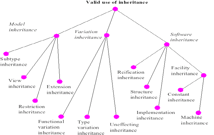
- Subtype - modelling some subset relation
- Restriction - instances of the child are instances of the parent that satisfy a specific constraint (e.g., square inherits rectangle)
- Extension - adding new features
- Variation - child redefines features of the parent
- Uneffecting - child abstracts out features of parents from at least one client view
- Reification - partial or complete choice for data structures (e.g., parent is a TABLE, reifying child classes are HASH_TABLE)
- Structure - parent is a structural property (COMPARABLE), child represents objects with property
is-a does introduce problems, however. Some phrases that contain the words "is a" are instantiation phrases, and some are generalisations. Generalisations are transitive, instantiation is not. So, when using is-a, you should take special care that you do not mean an instantiation instead of a generalisation relationship.
Class Diagrams
A UML class diagram describes the classes in a system and the static relationships between them. These static relationships are variants of:
- associations
- generalisations
Class diagrams also depict attributes and operations of a class, and constraints on connections.
Class diagrams can be used in three different ways:
- Conceptual modelling, drawn to represent concepts in the problem domain, and often done during analysis and preliminary design
- Specification modelling, drawn to represent the interfaces, but not implementations of the software
- Implementation modelling, drawn to represent code
The division between these perspective is "fuzzy".
Conceptual Modelling
- Concept - a real world entity of interest
- Structure - relationships between concepts
- Conceptual modelling - describing (using UML) concepts and structures of the real world
Class diagrams are commonly used for conceptual modelling. They are a way to model the business domain and capture business rules. They do not depict the structure of software, however!
An example conceptual model/class diagram might look like:
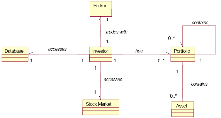
The conceptual model is used as the basis for generating a specification model. Classes appearing in the conceptual model may occur in the specification model, they may also be represented using a set of classes, or they may vanish altogether!
All OO methods hinge on being able to find the concepts and classes - this is much more critical than discovering actors or scenarios. It is the process of finding concepts that really drives OO development - use cases are not OO! It is important to note that we are not finding objects, as there are too many of these to worry about - rather, it is the recurring data abstractions that need to be found. There are no rules, but we do have some good ideas, precedents and known pitfalls.s
One way of introducing a concept is to use noun and noun phrases from the system requirements. This isn't very good, but does work as a first pass approximation. Many books take this superficial approach: "Take your requirements documentat and highlight all the verbs and all the nouns. Your nouns will correspond to classes and your verbs to methods of classes." This method is too simple-minded, however. It suffers from the vagaries of natural-language description, finds obvious classes but misses hidden ones and often finds totally useless classes.
When evaluating the usefulness of a class from this method, you must ask yourself the question: Is this class a seperate data abstraction, or are all operations on this class already covered by operations belonging to other classes, or "is the proposed class relevant to the system?" - this is answered based on what you want to do to the class.
The noun/verb approach often misses important classes based on the requirements are phrased. Rewriting a requirement can help, but you need to know what you are looking for to make sure it is in the rewritten requirement.
We need to be able to find interesting classes. An interesting class:
- will have several attributes
- will have several operations and methods (and at least one state-change method, usually)
- will represent a recurring concept, or a recurring interface in the system you are building
- will have a clearly associated data abstraction
Association vs. Generalisation
When planning associations between classes, how does a designer know how to use inheritance or client-supplier? The decision can be based on whether or not one is a more sensible modelling decision than the other, or on performance grounds. Generally, inheritance offers a bit more of a performance hit than client-supplier (though this also depends on how good an optimising compiler you have). To answer this, we need to consider substitution and dynamic despatch.
Generalisation becomes particularly useful when used with substitution and polymorphism.
Substitution is assigning one variable to an object of another type, allowing you to replace a general type with a more specific type. For example, if you had a variable p referring to an object of type Person and a variable e referring to an object of type Employee, and then did an assignment of p = e, this is perfectly legitimate, as variables are only references to objects, not the objects itself. When a client calls p.f, however, it can only call the features of Person, as the compiler would see attempting to access a method that belongs to Employee as an invalid function call and throw an error at compile-time.
Inheritance also introduces problems of method overriding. If you consider a class Person with a method display(), the display methods for Persons are probably not appropriate for Employees, since the latter have more and different attributes, so we can override the version of display() inherited from person and replace it with a new version for Employee.
When overriding occurs, the child class merely provides a new implementation of the method. If the signature matches that of an inherited method, the new version is used whenever it is called. In UML, there is no special syntax for overriden operations and some developers omit the operation in the child class if it is overriden, which can lead to confusion. The {leaf} constraint next to the name of an operation prevents overriding in subclasses.
There are constraints on overriding, however. Rules have to be obeyed in order to maintain substitutability and static typing in a language. The typical rules on overriding are that attributes and methods can be overriden by default and the overriden method must type conform to an inherited method. Additionally, the overriden method must correctness conform to the original (this is covered later in contracts).
Type conformance is language dependent, and Java implements the exact match rule, sometimes called "no-variance". Other methods of type conformance are contravariance, where a type is replaced by a more general type and covariance, where a type is replaced by a more specific type. Contravariance has not been demonstrated to be very useful, but it is relatively easy to implement. No variance is also trivial to implement, but it is often too restrictive for use (e.g., in Java, many casts to Object are made). Covariance is probably the most useful, but it can require system-level validity checks, which are very expensive. In UML, type conformance is a point of semantic variation.
Dynamic dispatch is very useful and is used to invoke methods applicable to the dynamic type (the type of object attached to a variable) of an object. During execution, a variable can be used to refer to objects of its declared (static) type or of any compatible type, e.g., children and their descendents.
The basic rule of association vs. generalisation is simple, a directed relationship represents "has-a" and a generalisation represents "is-a", however it is still sometimes difficult to decide which one to use. We can take the point of view that when the "is-a" view is legitimate, we can take the "has-a" view as well, however the inverse of this is not normally true.
Rule of Change
Associations permit change, whilst generalisations do not.
Do not use generalisation for a perceived is-a relationship if the corresponding object components may have to be changed at run-time.
Polymorphism Rule
Very simple: if we want to use polymorphism and dynamic binding, then we use generalisation.
Generalisation is appropriate for representing is-a relationships if data structure components of a more general type may need to be attached to references of a more specialised type.
Most people use UML class diagrams as described above, and they are the most useful type. They can be applied with a number of different programming languages. The more advanced concepts covered below are more challenging to use with specific programming languages, but the concepts are still useful.
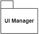
Packages
Packages can be used to group any collection of modelling elements (classes, objects, other packages, etc...). Relationships between packages can be expressed in terms of dependencies; a dependency exists between two elements if changes to one element (the supplier) may cause changes to the second element (the client). There are many type of dependencies in UML (association and generalisation are forms of dependencies).
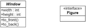
Stereotypes
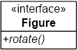
Stereotypes are the standard lightweight mechanism for extending UML. If you need a modelling construct that isn't UML, but which is similar to something that is, then a stereotype should be used. A stereotype is a textual annotation of diagramming elements. Many standard stereotypes exist, and you can define your own.
e.g., a UML interface:
Some built in stereotypes include:
- <<access>>: the public contents of a target package are accessible to the source package namespace
- <<create>>: a feature which creates an instance of the attached classifier
- <<friend>>: the source has access to the target of a dependency
- <<instantiate>>: the source classifier creates instances of the target classifier
- <<invariant>>: a constraint that must hold for the attached classifiers/relationships
Translating a stereotyped class into a programming language is a challenge. Not all stereotypes will be immediately translatable to all languages, e.g., <<friend>> in Java is difficult, but is easy in C++. A library of "patterns" is often needed. Tool support is also required for bespoke stereotypes, e.g., how will you make Visio support an <<RFID>> stereotype, not only syntactically, but also for code generation.
Aggregation and Composition
Associations represent general relationships between classes and objects. At the implementation level, they can be defined in terms of reference types. Further relationships are also provided with UML:
- aggregation: "part-of"
- composition: like aggregation, but without sharing
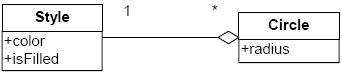
This aggregation relationship shows that an instance of Style is part-of zero or more instances of Circle. Style instances may also be shared by many circles. This is semantically fuzzy, as there is no implicit difference between this and association, and it can't be implemented in Java. It is advisable to avoid this unless you formally specify its meaning.
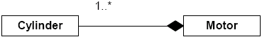
This composition relationship shows that a motor is composed of one or more Cylinders, and Cylinders are "integral parts" of Motors. The part objects (here, Cylinders) belong to only one whole and the parts live and die with the whole. These are sometimes called "value types" or "expanded types", such as in Eiffel.
Association should be used whenever you are in doubt over which relationship to use, and association can always be refined to more specific forms of relationships between modelling elements. Associations with 1..1 multiplicity can be considered equivalent to compositions (since they support cascading deletes too).
Interfaces and Abstract Classes
A pure interface provides no implementation, only operations are declared. An abstract class may have some implemented methods and fields, but not everything needs to be implemented.
Association Classes
Association classes can be used to add attributes, operations and constraints to associations.
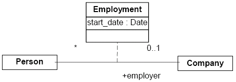
In the case above, an attribute could be added to Person showing the start date with a company, but this is really an attribute of the relationship between Person and Company.
The association class implicitly includes the constraint that there is only one instance of the association class between any two participating Person and Company objects. Otherwise, this must be stated explicitly.
Parameterised Classes
The notion of parameterised classes is present in Java, C++ and Eiffel. They let you define collections of an arbitary type, e.g., Set(T), Sequence(T), Binary_Tree(T), where T is a type parameter that must be filled in order to produce a type that can be used to instantiate objects.
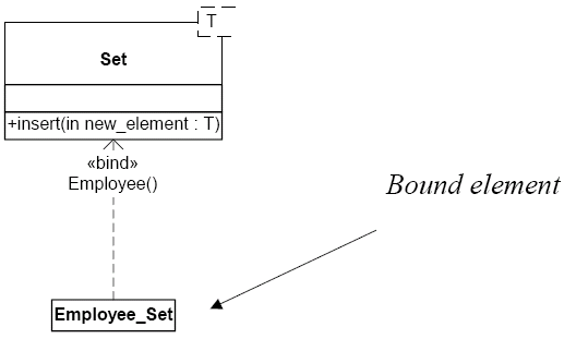
<<bind>> is a stereotype on the dependency and it indicates that Employee_Set will conform to the interface of Set. You can not add features to the bound element.
So far we have only considered how to model static system aspects. UML provides facilities for modelling behaviour, which in general is by considering objects and events, messages and reactions to events.
System Events and Operations
Systems are used by actors (e.g., users and other systems) and are built to respond to events - external stimuli generated by actors. When delineating the system borderline, it is often useful to find out which events are of interest to a system.
Operations are executed in response to a system event. The system has control over how it responds to events, and operation execution in UML is usually represented via messages.
UML provides diagramming notations for depicting events and responses - communication diagrams.
Communication Diagrams
Communication diagrams describe how groups of objects collaborate in some behaviour. Typically, a communication diagram captures the behaviour of a single scenario of use. It shows the number of objects and the messages that are passed among these objects within the scenario.
There are two main types of communication diagrams: sequence diagrams and collaboration diagrams.
Sequence Diagrams
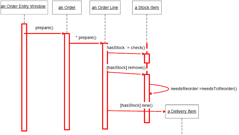
In sequence diagrams, objects are shown as boxes at the top of dashed vertical lifelines (actors can also be shown). Messages between objects are arrows, and self-calls are permitted. Conditions (guards) are used, as are iteration markers.
To show when an object is active, an activation box is drawn and the sender is blocked. Return from the call can be shown as well, but it usually clutters the diagram and confuses things if you do.
An external view of a system can also be represented using a sequence diagram.
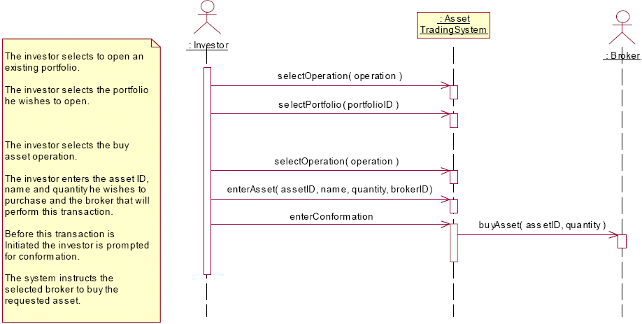
Sequence diagrams are traditionally constructed after system services and scenarios of use have been determined. They are good at showing collaborations among objects, not a precise definition of the behaviour. Statecharts are better suited to the behaviour of a single object.
Sequence diagrams are built by identifying events - are they generated by an actor, or the system itself? The focus is on capturing the intent rather than the physical effect (i.e., don't use them to flowchart).
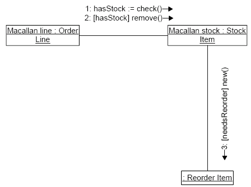
Collaboration Diagrams
Semantically, they are equivalent to sequence diagrams. Objects here are shown as icons, and they can be placed anywhere on the page/screen. The sequence of message firing is shown by the number of the messages. It is easier to depict object links and layout with collaboration diagrams and they are also a lot more compact. Sequence diagrams show sequences better, however.
In collaboration diagrams, different numbering schemes for sequences are permitted:
- Whole sequence numbers (as shown above) are the simplest
- Decimal number sequences (e.g., 1.1, 1.2, 1.2.1, 1.2.2) can be used to show which operation calls another operation
Control information (guards and assignments) can also be shown in collaboration diagrams as with sequence diagrams.
Object Diagrams
A collaboration diagram without messages is also known as an object diagram, and the relationships between objects are called links. An object diagram must be a valid instantiation of a static class diagram. Objects must have classes and links between objects must be instances of associations between classes. This can be used as a quick consistency check.
State Charts
Class diagrams and packages describe static structure of a system. Interaction diagrams describe the behaviour of a collaboration. However, we have not described the behaviour of a single object when it reacts to messages - this can be done using OCL (covered later) or statecharts. State charts describe all possible states that an object can get in to, and how the object responds to events.
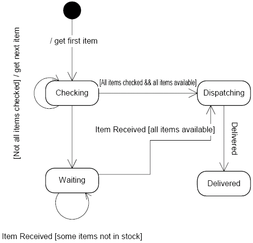
The syntax for a transition in a state chart is: Event [Guard] / Action. Actions are associated with transitions and are short, uninterruptible processes. Activities are associated with states, and may be interrupted. A guarded transition occurs only if the condition evaluates true; only one transition can be taken. When in a state with an event, a wait takes places until the event occurs.
Statecharts are good at describing the behaviour of an object across several scenarios of use. They are not good at describing behavior that involves a number of collaborating objects (interaction diagrams should be used instead for this).
It is not usually worthwhile to draw a statechart for every class in the system, so they should only be used for classes that exhibit interesting behaviour, e.g., UI and control objects.
Common Criticisms of UML
- Not writing code immediately often draws criticism of wasting time, however a short amount of time spent on modelling may save a great deal of time coding (See agile methods and extreme programming earlier on).
- UML is very complex (the syntax guide is 200 pages long). This is true, so most users only focus on a selection of the most useful diagrams.
- UML can easily produce inconsistent models (i.e., multiple views of the same system). Research and tool support is hoping to improve this.
Standards
UML is a de facto standard, that is, one produced by industry that aims to be practical and usable, but technically inferior to official standards. Standards are documented agreements containing technical specifications or other precise criteria. They are to be used consistently as rules, guidelines or definitions of characteristics, to ensure that products are fit for their purpose.
Other types of standards include de jure, which are official standards from a governing body (e.g., ISO, IET, ANSI, BSI) and are developed under consultation with stakeholders. They are usually slow to appear (often past the point where they would be useful) and because they represent compromises among different views, they are often hard to apply. A final type of standard is an in-house one, which only applies to a particular company.
Use Cases
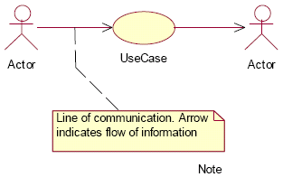
Use cases are commonly described as telling a story of how a user carries out a task to achieve a desired goal (functionality). A use case is a document that describes a sequence of steps of an actor using a system to complete a scenario. An actor is external to the system (i.e., it is a human operator or another system) and a scenario describes a complete sequence of events, actions and transactions required to produce or complete something of value.
Use cases are all about what an actor does, not how they or the system accomplishes it.
Actors can be broken down into primary actors, with goals, and secondary actors, with no goals, but interests, such as managers in a retail environment.
Use case diagrams are used to illustrate the relationship between a set of use cases and their actors. Their purpose is to allow rapid understanding of how external actors interact with the system, however, the diagrams are not the important thing.
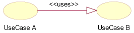
If one use case initiates or duplicates the behaviour of another use case, it is said to 'use' the second use case, and this is shown as:
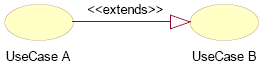
If one use case alters the behaviour of another use case, it is said to extend the second use case, and this is shown as:
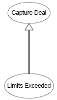
If one case is similar to another, but does a little bit more, then generalisation can be applied:
The difference between <<extends>> and generalisation is that with <<extends>>, the base use case must specify extension points.
Some guidelines to think about use case relationships are that it's usually easier to think about normal cases first and worry about variations afterwards. <<uses>> (sometimes called <<include>>) should be used when you are repeating yourself in two seperate use cases. Generalisation should be used when you are describing a variation on a behaviour that you want to capture informally. <<extends>> should be used when you more accurately want to capture a variation on behaviour.
Use cases can interact with any number of actors, and use cases are discovered by first identifying the actors. For each actor, you need to consider the scenarios that they might initiate (trigger). A common error that is made is representing initial system functions with a use case (e.g., create transaction, destroy record, etc...). Use cases represent services that may be implemented by multiple operations (i.e., a transaction) in a system. They are usually relatively large processes.
Use cases should also be created to deal with exceptions (e.g., in a retail environment and the card authorisation fails), which should be encapsulated in so called secondary scenarios. Alternatives also need to be considered in these secondary scenarios.
An Example Use Case Template
- Name: << An active verb phrase, describing the goal >>
- Context: << A longer description of the goal >>
- Actors:
- Primary Actors: << The Actor with the goal >>
- Supporting Actors: << Those with interests to be protected >>
- Preconditions: << Required state of world prior to Use Case >>
- Trigger: << What starts the Use Case, often Primary Actor >>
- Main Success Scenarios: << Steps >>
- Success Postconditions: << Holds for successful exit and achieves goal >>
- Secondary Scenarios: << Steps and postconditions >>
Use cases are good for modelling current work practices, describing transactional style systems (but are probably not the first choice) and uncovering business rules and error cases. They should be used with care, and scenarios should be kept free from design assumptions.
The Development Process
The UML provides a standard language for describing OO systems; it does not describe a standard development process. Reasons for this include a need to seperate concerns and recognising that different development processes will be used in different problem domains by different people.
It is possible to identify a fairly typical view of best practices, basic activities and models, based on an iterative, use case driven development process. RUP (discussed earlier) is an example of this.
Interative, Use Case Driven Development
An iterative life-cycle is based on successive enlargement and refinement of a system through multiple development cycle of analysis, design, implementation and testing. Each cycle tackles a relatively small set of requirements, proceeding through the cycle. The system grows incrementally as each cycle is completed, in contrast to the classic waterfall model. In iterative development, we have the advantages of a reduced complexity and the generation of early feedback.
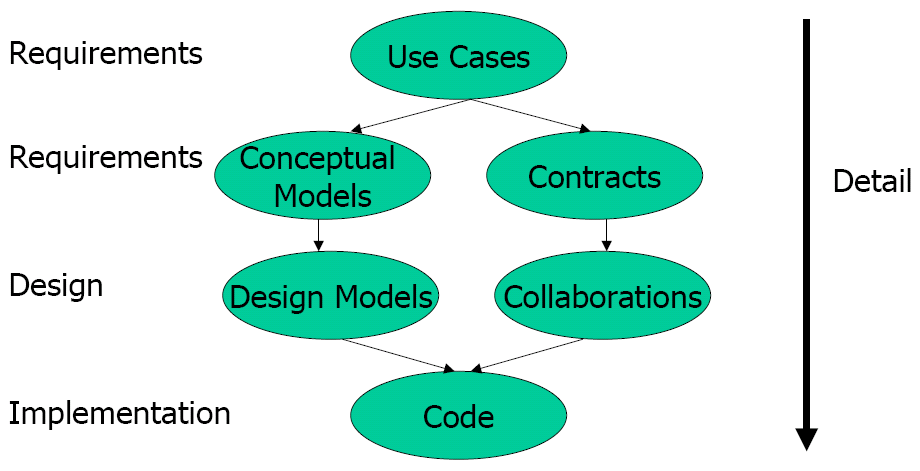
The basic (rational) process has 6 stages:
- Use case modelling
- Each use case (scenario) is refined and explained using interaction diagrams
- In parallel, class diagrams are produced
- Complex interactions from step 2 are refined using collaboration diagrams and statecharts
- Specification class diagram is produced
- Code is generated
Design by Contract
RUP, or use case driven development helps us identify features that stakeholders want, identify objects and collaborations that implement these features, identify classes that provide the structure that enables collaboration and identifies operations (the building blocks of operations). However, it does not help us describe the behaviour of operations.
Assertions
An assertion is a boolean expression or predicate that evaluates to true or false in every state. In the context of a program, assertions express constraints on the program state that must be true at a specified point during execution. In a model/diagram, they document what must be true of a implementation of a modelling element. Assertions are typically associated with methods, classes and even individual program statements and are useful for helping to write correct software, since they specify what is expected behaviour, as well as for documentation of interfaces and debugging and to improve fault tolerance.
Pre- and postconditions are assertions associated with methods of a class. Preconditions are properties that must be true when the method is called and postconditions are properties that must be true when the method returns safely. They can both be optional (in which case the assertion is just True), and in this case, an optional precondition implies that "there are no constraints on calling this method", and an optional postcondition implies that "the method body can do anything, as long as it terminates".
Pre- and postconditions can be viewed as a contract that binds a method and its callers/clients: "If you (the client) promise to call me (the method) with the precondition satisfied, then I guarantee to deliver a final state in which the postcondition holds." The caller thus knows nothing about how the final state is produced (abstraction), only that they can depend on delivery. The method and its implementer need to only worry about cases where the precondition is true (and none other).
However, if a client calls a method when the precondition is false, then this precondition violation is the client's fault. This is extremely helpful in tracking down errors, as if a precondition is failed, the supplier code does not need to be analysed. Formally, the contract says nothing about what should be done if a precondition fails, so any behaviour (infinite loop, exception handler, return error message) is acceptable.
Contracts are specifications of what a method should do under particular conditions. So, given a contract, you can write an implementation that satisfies it. This form of documentation is more precise than just class interfaces. Run-time checking for correctness can be implemented, and they also provide a basis for testing and formal proofs.
In addition to pre- and postconditions, we also have class invariants, which are global properties, preserved by "all" methods and instances of the class. Despite its name, however, the invariants does not always need to be true. The constructors must leave the object in a legal state satisfying the invariant, they can not assume the invariant is automatically initialised. Any legal call made by a client must start from a state satisfying the invariant and must end up in such a state that also satisfies the invariant. Private methods can do what they like, but if they terminate in a state where the invariant is false, then clients can not use the object. This is sometimes too inflexible, however.
The effect of an assertion at run time should be under the control of the developer. Checking assertions takes time (especially invariants and postconditions), but in testing and debugging, these assertions are very important and helpful. For production releases, assertion checking may want to be turned off to improve performance.
We need to consider what happens to assertions with inheritance, however. In general, assertions are inherited with the features or classes to which they apply, and the invariants are anded together. However, if two contradictory assertions are inherited, this causes a fallacy and the object will never be in a safe state.
Child classes can also override method implementations from a parent, but what if the parent method has a contract that is inherited? There are two alternatives, which is to replace the inherited implementation, but keep the contract (e.g., to provide a more efficient implementation, or an implementation that does more than the original), or to modify the contract and the implementation (because the contract may not say exactly what you want, but complications may arise with things such as substitution).
Contracts can not be invalidated or broken by overriding, otherwise clients can not rely on the methods' results. You can do at least what the original contract could do, but you can also do more. This leads us to the rules for assertion and overriding:
- The inherited contract can not be broken/contradicted
- The inherited contract may be kept unchanged; this guarantees that it is not broken (used for changing the method body/implementation details)
- The @pre may be replaced by a weaker one
- The @post condition may be replaced by a stronger one
Rules 3/4 imply that if you want to change the contract under inheritance, you can replace it with a subcontract, where every behaviour of the new contract satisfies the original.
To use subcontracting effectively, a compiler has to check that preconditions are weakened and that postconditions are strengthened. This is inefficient for real programs. An efficient implementation is to use a low-tech language convention based on the observations that for assertions α, β, γ: α implies (α ∨ γ) and (β ^ γ) implies β. i.e., accept weaker preconditions only in the form (α ∨ γ) and accept stronger postconditions only in the form (β ^ γ).
In languages such as Java with iContract or Eiffel, only new clauses are specified in the overriden method and new @pre clauses are automatically or-ed with any inherited precondition clauses and any new @post clauses are automatically and-ed with any inherited postcondition clauses. The overridden contract is automatically a subcontract in this case, and no theorem proving needs to be done.
UML is primarily a graphical notation, and uses text for labels and names. Text is also used for writing constraints, a restriction on state values. Types are a form of constraints, and constraints are how design by contract is implemented in UML. Constraints are also useful for resolving limitations with UMLs expressiveness.
UML supports an informal notion of constaint called a note, which can hold any piece of information and is expressed as a string attached to a modal element. There are no restrictions as to what can go in a note, but to write formal (machine-checkable) constraints, we use the standard constraint language OCL.
OCL
OCL, or the Object Constraint Language, is a constraint/assertion language for OCL. It is used for writing general constraints on models and also for design-by-contract. It can be applied to any modelling element, not just classes.
OCL has some issues, however. It has a programming language like syntax (similar to C++), but is easy-to-use by non-formalists. There are no formal semantics, it is ambiguous and in places it can be cumbersome. OCL is used in the UML metamodel.
The essential capabilities of OCL are the context, specifying which modal element is to be constrained; navigation expressions, navigating through models to identify objects that are relevant to a constraint, which can be used to constrain values of attributes and related objects; and expressions, which are asserting properties about relationships between objects.
For examples of
navigation expressions
see the lecture slides.
Navigation expressions provide the means for referring to objects that are linked to a specified context object. Linked objects are obtained starting from the context object. Links are followed to gain access to other objects of interest (similar to references in Java/C++/Eiffel), but complexity arises when collections (e.g., sets, sequences, bags, etc) are navigated.
OCL supports a number of basic types and typical operations upon them, e.g., Boolean, Integer, Real and String. Collection, Set, Bag, Sequence and Tuple are basic types as well and iterative operations and operators exist for making use of these. Every class appearing a UML model can also be used as an OCL type. Type conformance rules are as in UML, i.e., types conform to supertypes, i.e, Set, Bag and Sequence conform to Collection.
Predefined operations available on all objects include:
- oclIsTypeOf(t : OclType) - true if self and t are of the same type.
- oclInState(s : OclState) - true if self is in the state specified by s. s is the name of some state in the statechart for the class.
- oclIsNew() - true if used in a postcondition and the object is created by the operation.
The logic for OCL is actually three-valued, as an expression can evaluated to true, false or undefined. e.g., illegal type conversions return undefined, and taking the first() element of an empty sequence.
For truth tables, we consider that an expression is undefined if one of its arguments is undefined, except:
- true OR anything is true
- false AND anything is false
- false IMPLIES anything is true
If a navigation expression denotes objects retrieved by following links, then depending on multiplicities of association, the number of objects retrieved may vary. When a navigation expressions can return more than one object, it returns a collection (a set or a bag) - iterated traversals provide bags, single traversals provide sets. As of UML 2.0, collections can be nested.
As navigations can be composed, more complicated paths through a diagram can be denoted. These are evaluated in a step-by-step manner. For example, for self.department.staff, self.department gives a set of departments, and then .staff is then applied to each element of the set, producing a bag of people.
Operations and attributes defined for classes in a model can be used in OCL expressions, and collections come with some built in operations, accessible using →, typically producing bags. e.g., sum() is applicable to numerical collections and asSet() which converts bags to sets, removing duplicates.
select() is also a built-in operation for picking out specific objects from larger collections (a quantifier). e.g., to pick out all employees with a salary greater than £50,000: context Company inv: employees→select(p:Person|p.contract.grade.salary>50000). Further navigations can be defined on the result of the select.
Similarly, the collect() operation takes an expression and returns a bag containing all values of expression. e.g., to return the age of all employees in the department: context Department inv: staff→collect(p:Person|p.age()). You need to avoid dropping name and type of bound variables, as this can easily lead to ambiguity - the OCL guide is quite careless on this.
Other iterative constraints defined on a collection include forAll() (returns true if every member of the collection satisfies the boolean expression), exists() (true if there is one member of the collection satisfying the boolean expression), allInstances() (returns all instances of a type, e.g., Grade.allInstances→forAll(g:Grade|g.salary>20000). allInstances() should be used very carefully, as it is not always necessary to use it, and it is often difficult to implement it.
OCL can also be used to write arbitarily complex constraints, which can correspond to class invariants.
The usual laws of design by contract should be followed with UML and OCL (preconditions weakened - or; postconditions strengthened - and; new clauses and'ed to the invariant). OCL does not require that you follow these rules, but it is strongly recommended. Modified contracts must maintain consistency.
Generalisation relationships in OCL are not navigable, and they do not usually feature in writing constraints, but generalisations may be constrained.
Testing
Typical development projects include a substantial amount of time and money spent on testing. On average, this is 40-60% of the overall project cost. It is unrealistic to expect to get everything right from the start, as there is not enough time to get the requirements perfect, clients can change their minds and there might be extremely strict dependability requirements, so a testing phase will always be required to show that the project meets its requirements.
Testing has come a long way with the since the birth of software engineering. The first view of testing was a "novice" view from the 1970s, where testing is basically debugging. This is a "happy fantasy land with elves, pixies and gremlins". This developed into an increasingly mature view in the 1980s which is where you try to show that software does not work (a shift from testing whether software does work, to proving it does not work - try to break the software and check it handles errors correctly) and in the 1990s where testing that reduces the risk of not meeting requirements or quality targets - non-functional requirements. This evolved into the mature view taken today, where testing and quality is a state of mind. Code tests are not the only testing done to check correctness - questions such as "did you build the right system" and "did you build the system right" are the ones that are asked. Testing and correction is done at all stages at the lifecycle.
Verification is checking that the system has been built correctly, such as verifying against the metamodel for UML or the language specification for code. Validation is checking that the right system has been built and it is what you want - assertions and pre- and postconditions are used to do this. Verification can be done by the development team, but validation should be done by people outside the team, as it is hard to be objective when you were involved in development.
Verification of the model should be done at each level of abstraction and validation should be done between each level - this checks that the system meets current requirements.
Certification is checking against a "benchmark", and it is done in situ over time, e.g., moving from beta to release candidate to final, etc... Certification shows that the system performs adequately when put into action. Validation, verification and certification can be carried out by systematic, planned testing and argument.
Validation, verification, testing and certification are all part of the quality assurance phase of a project. QA consists of:
- a definition of what is considered "acceptable quality" for the product being considered
- a definition of the QA process or processes that will be followed to ensure quality (e.g., reviews)
- application evidence (e.g., test data, the results of reviews, expert assessments of quality)
- analysis of the evidence (i.e., how well did we meet our goals)
The principle of ALARP - as low as reasonably possible - is used in QA. This is making sure that everything is as safe as reasonably possible. For consumer software, low might not be that low, but for safety-critical systems, it probably will be very low.
Testing is one of the key techniques in QA, and by ensuring that you are aware of the current version of requirements, VVC becomes a lot easier.
Preparing for testing all starts with the requirements, which are used to start deriving tests. These tests need to be relatively stable. Certification is done with acceptance tests, to demonstrate that the "adequacy" requirements are met. Validation is performed by testing the system before installation, to show that the design has been met. Verification is performed by unit and module testing to demonstrate that code meets the design.
V Model
The V model is a development model where a testing mentality is demonstrated at all stages of the design lifecycle.

A unit is a component of interest in your system, e.g., a class, a package, function, etc... Unit tests usually consist of a few hundred lines of code aimed towards breaking the design, and these are devised as part of the design process. Development of unit tests is an interative process, as new elements of the design are added and improved, the unit tests must be re-run and errors corrected.
Integration testing is testing that when we "glue" together these units, then they behave sensibly. It makes the assumption that we have successfully unit tested the whole system. Integration testing tests large components against their specifications. It is designed to check that all units are used and all input errors are properly handled, and that all specified functionality is provided and it all works properly together.
Unit testing can be typically done in team, but integration testing may involve code or designs from another team. The precise interfaces of units need to be clearly specified. Often, specialised testing teams are employed to deal with integration testing so as to avoid team conflicts (and also to speed up the process).
For acceptance tests, the entire system (including hardware) is tested against the requirements. Acceptance tests consider the system as a whole, as well as performance, security, configurability, start-up and recovery issues (i.e., the non-functional requirements). Tests derived from the specification are executed against the system in the client's environment. The certification process often requires "correct" operation over a predefined period.
Test-Driven Development
In its purest form, this is where you write test drivers and test cases (i.e., test data and expected results) before you write the code, although obviously some modelling and the interface specification will need to be done.
In general, whenever you make a change to your system, rerun your tests before you check the changed code into the repository. If the system fails to build at the end of the day (the system should be built once a day), it will be easy to identify the culprits.
Testing on a class can be done using pre- and postconditions and invariants. Preconditions on the constructor should be implemented as invariants (as it is impossible to check an attribute on an object before it exists and invariants are checked after the object is created). It is important to check when you are writing assertions that you are writing the correct thing, and testing for tautologies and fallacies are good ways of checking for this.
When writing test cases, exception handlers are used to handle errors generated by calling a method, so the test case can return true if the test case passes. When dealing with contracts, there are general rules to follow when exceptions are raised:
- Run-time assertion violations are manifestations of bugs in the program (even if the violation is due to environmental issues outside of your control, you still have to anticipate and deal with them).
- A precondition failure means that the client is at fault, and that is where the bug lies
- A postcondition failure is the suppliers' fault, and that is where the bug lies
However, the mere fact that a test passes does not mean that the software is correct, as an analysis error when designing the test case could have occured, so an incorrect implementation and the wrong test can collaborate (especially if the wrong assumption or interpretation is made of the requirements) to make the test result "correct".
One of the key goals of software engineering is to make bug free code, however sometimes intentional bugs are introduced e.g., Excel replicated a bug in leap handling from Lotus 123, so they could use the same date serial number scheme as Lotus 123 and increase compatibility.
Testing aims to guarantee that a system is fit for a specific purpose. It must be effective and also cost-effective and thus testing requires proper planning. We must anticipate a certain amount of testing, but it is often desirable to minimise costs - it is relatively easy to fix mistakes early on in development, but less so as development continues. Organisations must decide how much it is worth to fix faults.
Research has shown that it is impossible to fully test a system, or fully prove that it's correct ("Testing can never prove the absence of errors, only their presence" - Dijkstra), so research now concentrates on testing/proof strategies that give the greatest confidence for the least effort. The testing process must be systematic and documented which will help in future planning and estimation.
A common cycle of testing looks like:
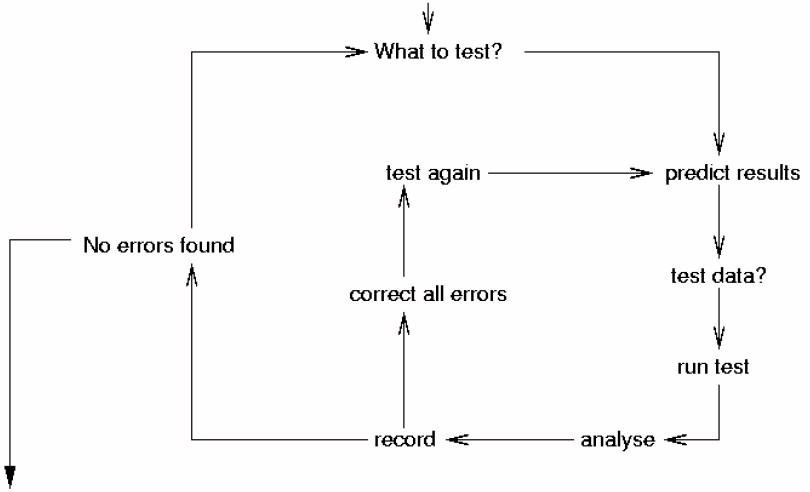
There are two main types of testing that can be performed: static testing (models and code are analysed for correct construction - no code is actually executed, e.g., for rules such as no null-pointer dereferencing); and, dynamic testing (executes the code against sample data, the results of which are compared to predictions from models or code). Code is typically analysed in advance to acquire suitable test inputs and expected outputs.
Path analysis is a commonly used technique applied late in design or during implementation. A program defines a set of paths through the code based on its control structure or in terms of how variables are used, e.g., every variable in a program must be introduced, intialised, destroyed and used. The points in a program where these events occur are marked and then a tool is used to check that each event occurs the right number of times for each variable. This is usually implemented using some sort of graph structure.
Paths can also be used to analyse control structure, as paths represent loops, sequencing, choice, etc... Some things that can be checked for are dead code (i.e., all segments of a program can be reached) and that loop conditions allow termination.
"Rational" testing is dynamic testing based on test cases, but this clearly can not test all possible paths. Domain testing aims at using models to reduce the number of tests needed (e.g., look at the attribute types in UML classes and extract extreme values, or look at guards in sequence diagrams or state charts to extract values for exercising all branches).
Statistical testing, which is based on usage models (i.e., what does a typical user/archetype do with the system), also has uses. Test cases are generated from usage models focussing on critical or problematic scenarios. Random tests are also included to attempt to exercise code that is most often accessed.
Testing must also be able to deal with changes to requirements, which spawn changes to models and code. Regression testing controls the amount of re-testing carried out in response to change. The original system tests are saved and documented. Changes are traced through to the tests and changed results predicted. Tests should then be re-run, unchanged parts should give the original results, but changed parts should give the predicted results.
Testing and recording of results needs to be systematic, and this is necessary for estimation for future projects and maintenance. This is made easier with proper planning and recording of testing results. For validation, it is vital to number requirements and cross-reference design decisions to those requirements. Verification, for comparison, is exercised against programs. It must be defined early on what is an acceptable level of testing, and how much detail to record.
Acceptability may not require 100% success, but there needs to be a record of which tests passed and which tests failed. Justifications must be made for failures that were condoned, and any modifications to the system must be fully documented.
By defining early on the goals for success, this helps you know when you have succeeded, even though sometimes the goal may seem like a moving target. Not all projects will succeed by building a complete system, and not all projects will succeed by writing a formal specification and refining it into C.