The Rise of Networks
Until the 1980s, computer systems were large and expensive, and there was no meaningful way to link them together. The 1980s, however, saw two important developments - powerful microprocessors and higher-speed networks (LANs/WANs now up and over a gigabit in speed). More recent developments including research are scalable cluster-based computer (e.g. Beowulf) and peer-to-peer networks (e.g., BitTorrent, SETI@Home, etc). The result is networked computers.
It is now feasible to design and implement computing systems with large numbers of networked computers. Advantages to this include shared resources, such as hardware (file stores, printers, CPU, etc) and software (files, databases, etc), to speed up computation (partitioned computations can have parts excecuting concurrently within a system), reliability (if one site fails, others may be able to continue) and easier communication.
Network Protocols
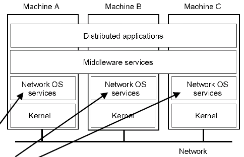
Seperate machines are connected via a physical network, and computers pass messages to each other using an appropriate protocol. Networking operating system services interface to the network via the kernel and contains complex algorithms to deal with transparency, scheduling, security, fault tolerance, etc. They provide peer-to-peer communication services and user applications directly access the services, or the middleware.
Middleware is a high level of OS services. Protocol is a "well-known set of rules and forats to be sued for communications between processes in order to perform a given task". Protocols specify the sequence and format of messages to be exchanged.
We can consider a protocol that allows the receiver to request a re-transmission across a data-link (on message error):
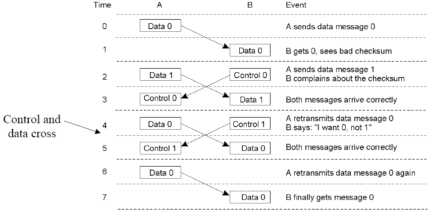
This protocol is inefficient due to a cross over of data and control messages. Steps 6 and 7 are not needed.
Protocol Layers
Protocol layers exist to reduce design complexity and improve portability and support for change. Networks are organised as series of layers or levels each built on the one below. The purpose of each layer is to offer services required by higher levels and to shield higher layers from the implementation details of lower layers.
Each layer has an associated protocol, which has two interfaces: a service interface - operations on this protocol, callable by the level above and a peer-to-peer interface, messages exchanged with the peer at the same level.
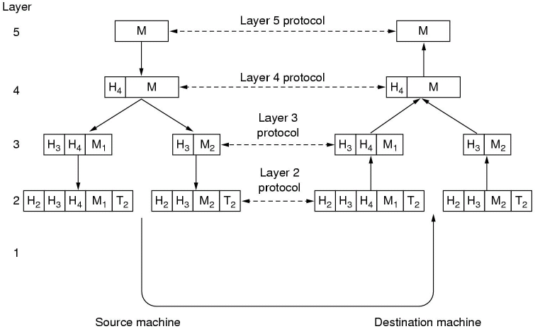
No data is directly transferred from layer n on one machine to layer n on another machine. Data and control pass from higher to lower layers, across the physical medium and then back up the network stack on the other machine.
As a message is passed down the stack, each layer adds a header (and possibly a tail such as a checksum, although this is most common at the bottom of the stack) and passes it to the next layer. As a message is received up the stack, the headers are removed and the message routed accordingly.
As you move down the stack, layers may have maximum packet sizes, so some layers may have to split up the packet and add a header on each packet before passing each individual packet to the lower layers.
Some protocol design issues include identification (multiple applications are generating many messages and each layer needs to be able to uniquely identify the sender and intended recipient of each message), data transfer alternatives (simplex, half and full duplex), EDC error control (error detection and correction - depends on environment e.g., SNR and application requirements), message order preservation and swamping of a slow receiver by a fast sender (babbling idiot problem, when a failed node swamps a databus with nonsense).
We can also consider two types of protocols, connection vs. connectionless. Connection orrientated services are where a connection is created and then messages are received in the order they are sent, a real world analogy is the POTS. Connectionless services are where data is sent independently. It is dispatched before the route is known and it may not arrive in the order sent, a real world analogy here is the postal system.
OSI Reference Model
The ISO Open Systems Interconnections (OSI) reference model deals with connecting open networked systems. The key principes of the OSI are:
- layers are created when different levels of abstraction are needed
- the layer should perform a well defined function
- the layer function should be chosen with international standards in mind
- layer boundaries should be chosen to minimise information flow between layers
- the number of layers should be: large enough to prevent distinct functions being thrown together, but small enough to prevent the whole architecture being unweildy
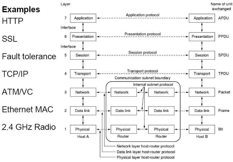
| Layer | Description | Examples |
|---|---|---|
| Application (APP) | Protocols that are designed to meet the communication requirements of specific applications, often defining the interface to a service. | HTTP, FTP, SMTP, CORBA IIOP |
| Presentation (SECURITY) | Protocols at this level transmit data in a network representation that is independent of the representations used in individual computers, which may differ. | SSL, CORBA Data Representation |
| Session (ERRORS) | At this level, reliability and adaptation are performed, such as detection of failures and automatic recovery. | |
| Transport (TRANS) | This is the lowest level at which messages (rather than packets) are handled. Messages are addressed to communication ports attached to processes. Protocols in this layer be be connection-orrientated or connectionless. | TCP, UDP |
| Network (ROUTING) | Transfers data packets between computers in a specific network. In a WAN or an inter-network this involves generation of a route passing through routers. In a single LAN, no routing is required. | IP, ATM virtual circuits |
| Data link (DATA) | Responsible for transmission of packets between nodes that are directly connected by a physical link. In a WAN, transmission is between pairs of routers or between routers and hosts. In a LAN it is between a pair of hosts. | Ethernet MAC, ATM cell transfer, PPP |
| Physical (WIRES) | The circuits and hardware that drive a network. It transmits sequences of binary data by analogue signalling, using AM or FM of electrical signals (on cable circuits), light signals (on fibre optic circuits) or other EM signals (on radio or microwave circuits). | Ethernet based-band signalling, ISDN |
Messages and headers combine to form packets - the bits that actually appear on the network.
TCP/IP Reference Model
The TCP/IP reference model originated from research in 1974 using the ARPANET (predecessor to the modern Internet). TCP/IP does not have session or presentation layers, which are only really needed in applications with specific requirements, and the data link and physical layers are combined to form one layer.
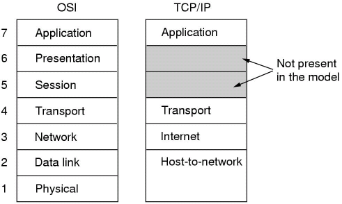
Protocols within the TCP/IP model include Telnet, FTP, SMTP and DNS at the application layers, TCP and UDP in the transport layer, IP in the network/Internet layer and ARPANET, SATNET, AX.25 and Ethernet in the physical/data-link layer.
The OSI and the TCP/IP models both have advantages and disadvantages. For example, the OSI model is well defined with the model before the protocols, whereas the TCP/IP model defined protocols first and then retrofitted a model on top. The number of layers is also different, although both have the network, transport and application layers the same. There are also different levels of support for higher-level services - these are the key differences. OSI supports connectionless and connection-orrientated communication in the network layer and connection orrientated only in the transport layer, whereas TCP/IP supports connectionless in the network layer and both in the transport layer, so users are given an important choice.
OSI suffers from the standard criticism that can be applied to all ISO standards, which is that it was delivered too late, it is over complicated and developed from the viewpoint of telecoms. Additionally, the implementations of it are poor when compared to TCP/IP as implemented on UNIX. Additionally, politics were poor, as it was forced on the world, and was resisted in favour of UNIX and TCP/IP.
The TCP/IP model has the problem of only being able to support TCP/IP protocols, whilst the OSI model can include new protocols. There is very little to distinguish between the data link and physical layers, which do very different jobs. TCP/IP is the result of hacking by graduate students, so there is little design behind it.
Middleware
Middleware alters the OSI model by replacing session and presentation layers with middleware protocols. In terms of the TCP/IP model, middleware protocols are placed between the application and transport layers. It is a good place to augment TCP/IP with dependability features, e.g., security and fault tolerance.
Middleware protocols abstract away from the difficulties of using raw UDP and TCP, and allow high-level IPC to occur. TCP is connection-based, so a connection needs to be established and closed down before messages can be sent. Messages are sent using the send and receive primitives, and can be used synchronously or asynchronously. Destinations of messages are specified as a tuple of IP address and port as dictated by TCP and UDP.
Sockets
A common implementation of this kind of middleware is using the "socket" abstraction. On UNIX-based systems, two type of sockets exist, ones in the UNIX domain, for local sockets tied to the VFS and ones in the INET domain, for processes on different machines. Different types of sockets also exist: SOCK_STREAM creates a TCP-based socket, SOCK_DGRAM for a UDP based socket and SOCK_RAW to handle other socket types (bypasses the TCP/UDP stage and uses the IP level directly).
Common socket operations include:
- socket(domain, type, procedure) - create a socket
- bind(s, port) - associate the socket s with a specified port
- listen(port, backlog) - server listens for connection requests on a port
- connect(s, serverport) - client connects to a server using socket s
- accept(s, clientport) - server accepts connection
- sendto(s, data, clientport) - client/server sends data to a port
- receive(ip, port) - client/server receives data from a port
The sockets abstraction is extensively used and realises many application level services, such as FTP, Telnet, HTTP, etc...
Most client-server communication is synchronous (the client blocks until the server replies), and acknowledgements are redundant, however asynchronous communication allows clients to continue without waiting (e.g., when no reply is expected from the server, or the client accepts the reply when it arrives).
Typically, request-reply type communication is mapped to TCP, as UDP may get omissions, lost replies, duplicates, unordered messages, etc... Using UDP/TCP in this way means distribution is apparent to the application, but one of the goals of distributed systems is transparency. Middleware provides a transparent layer between the application and transport protocols.
Remote Procedure Calls
Remote procedure calls (RPC) provides a higher level of abstraction than sockets. A client program calls a procedure in a server program (synchronous if a return value is required, otherwise asynchronous), and parameters have to be passed by value, as references are useless on another machine.
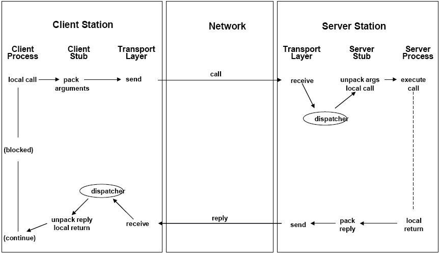
The dispatcher is required to map incoming calls onto the relevant procedure, and in the client to map an incoming reply message to the relevant stub procedure. The interface compiler generates a number (or name) for each procedure in the interface, which is inserted into the call message by the client stub procedure, and the server uses it to identify which procedure to call. In single-threaded clients, this is very slow as RPC must be done serially, but multi-threading clients have huge increases in throughput, as the program will not block.
In order to implement failure recovery, the server generates a unique ID for each remote procedure, and all RPCs must include the appropriate ID. The ID can then be used to detect failed server processes (by the dispatcher on the server) using a variety of techniques, and on the restart of the server process, a new ID is created, and the call with the stale ID is aborted. In the case of client failure, the server must be able to "roll back" (or perhaps do nothing if the semantics require it) to a previous state.
The OSI model is implemented into the network stack as demonstrated below:
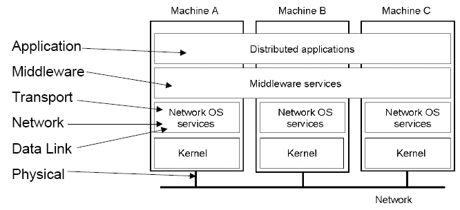
In the many implementations, however, the network and data link layers are often directly supported by hardware, leaving transport in the network OS services.
External Data Representation
We have the issue where hosts involved in communication may have different architectures and therefore representing data differently, so data needs to be converted between the sender and receiver representations. This is accomplished by the presentation layer in the OSI model.
The process of encoding and decoding application data and messages is called marshalling and unmarshalling.
We only consider lower level representations (integer lengths and big-endian vs. little-endian, IEEE754 floats vs. non-standard ones, string encoding, arrays, structures, etc) and not the higher level representations (e.g., images, video, multimedia documents, etc) which is dealt with at the application level.
Negotiation is required to change base types into a common format (e.g., 32 bits for integers), structures and arrays must be packed for transport, and more complex types (such as pointers), must be linearised. The most common conversion strategies are to use a common/canonical intermediate form, or to use a receiver-makes-right system. Tagging data helps this, as a common interface is used across a range of implementations.
Failure Semantics
In order to implement failure recovery, the server generates a unique ID for each remote procedure, and all RPCs must include the appropriate ID. The ID can then be used to detect failed server processes (by the dispatcher on the server) using a variety of techniques, and on the restart of the server process, a new ID is created, and the call with the stale ID is aborted. In the case of client failure, the server must be able to "roll back" (or perhaps do nothing if the semantics require it) to a previous state.
Different types of failure semantics include: Maybe (Best Efforts) Call Semantics, where the request is sent only once, and it is unknown what happens if the request times out, and unreliable networks may duplicate requests, and the state of the server is not reliable. Another type is At-Least-Once Call Semantics, where the client retries up to n times, so if the call succeeds the procedure has been executed at least once, however depending on the failure modes, this could be more.
At-Most-Once call semantics guarantees that the remote procedure is executed no more than once, but may only be partially complete. Here, the server tracks request identifiers and discards duplicates. The server must buffer replies and retransmit until it is acknowledged by the client. Transactional call semantics guarantees the procedure is executed completely once or not at all (i.e., no partial completion). The server must offer atomic transactions for each RPC, to take it from one consistent state to another consistent state, otherwise other RPCs using the data may get an inconsistent state.
Physical Networks
Physical Layer
The basis of data communication is that of some variation of a physical property of the communication medium, e.g., voltage on coaxial cable, pulsing light down fibre optics or RF propagation through the atmosphere.
At the physical level, we deal with communications at a bit level, and this is probably the most difficult layer to deal with, as physical hardware sends or receives raw bit streams and bit streams tend not to be error free.
Encodings such as non return-to-zero (NRZ) are used as electrical failure is easier to detect and signal-to-noise ratio is improved; here, 0 is -5V and 1 is +5V. The Manchester encoding improves the SNR further as an alternating signal is used - a '1' is represented by a full cycle of the inverted signal from the master clock.
The introduction of fault tolerance at this layer makes transparency difficult - the session layer is supposed to be responsible for fault tolerance, but this can only really be done with a fault model (i.e., a knowledge of errors due to transmission at the physical layer).
A limit on the data rate is placed by the sampling frequency. The Nyquist Samping Theorem (developed by Harry Nyquist working at Bell Labs) states that in order to be "perfectly" represented by its samples, a signal must be sampled at a sampling rate (or frequency) equal to at least twice its frequency. Other factors that affect data rate include the SNR and attenuation.
Other issues at the physical layer include latency (delay between sending and data becoming available at destination), message transmission time and throughput (the total volume of data across a network in any given time).
Data Link Layer
The data link layer builds the bit stream into frames of data.
The start and end of frames can be denoted by time gaps, however we then have the problem of missing bits - how do we signify the difference between the end of a frame and an error. We could denote a time gap with a certain sequence (e.g., CAN uses 6 consecutive equal bits), but this sequence could also indicate failure and "real" data has to be stuffed (insertion of an alternate bit pattern based on a pattern known to both sender and receiver that the receiver ignores) to prevent n equal bits being misconstrued as an error or time gap.
Other ways of implementing frames is by using a character count, start/end characters and this can be combined with parity checking or CRC checks.
RS232
Standards such as RS232 are point-to-point standards, which specify mechanical, electrical, functional and procedural interfaces. RS232 utilises a number of copper wires to connect two nodes, and what signals on these wires mean. Unidirectional hardware control lines are used to control flow.
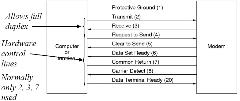
On RS232, communications normally occur using either a 7 or 8 bit byte, followed by an optional parity bit or stop bit. Both ends have to be configured in the same manner for communication to occur, however. RS232 has no real real error control, so the data-link layer usually includes some kind of basic protocol.
For RS232, transfer of data from source to destination occurs by an unacknowledged connectionless service (the source sends independent data frames to the destination), an acknowledged connectionless service (the source sends independent data frames to the destination with acknowledgement returned) or an acknowledged connection-orrientated service (the source and destination establish connection and send numbered/sequential frames). The latter is more reliable than the former.
Other checks (such as sliding window protocols) can be used, but are normally implemented at higher levels of the network stack.
Other issues we should be considering when dealing with physical networks include:
- Scalability - can it cope with a growth in traffic, clients, physical size, etc...
- Reliability - minimising the impact of errors introduced by the network, in order to avoid wasted traffic
- Security - ability to secure communication channels, e.g., firewalls or frequency hopping
- Mobility - access to network, wireless network, etc...
- Quality of Service (QoS) - meeting of deadlines, especially for multimedia applications
There are also different types of network to consider, such as LANs (local area networks), WANs (wide area networks - typically used to link different LANs together) and MANs (metropolitan area networks, normally implemented like LANs, but over a larger area). As networks get bigger, data transfer rate tends to decrease.
We can also consider wireless networks, such as WLANs (IEEE802.11a/b/g and are now often used in the place of LANs), PANs (wireless personal area networks, such as Bluetooth to phone, PDA, etc) and mobile phone networks (e.g., GSM).
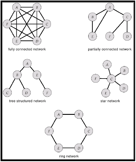
In large networks, packets may visit intermediary nodes before it reaches its intended destination, so the topology of a network is critical and factors such as installation cost, communication cost and availability should be considered. Common topologies for point-to-point networks are demonstrated below:
Broadcast Networks
In addition to point-to-point networks, we can also consider broadcast networks, which share a single communication channel. Here, messages are broken into packets which are broadcast to all on that channel, and when a packet is received, a computer examines the data (which contains a destination address) and discards it if it is not relevant.
Multicasting is a special case of this, and can be implemented in point-to-point networks also. Multicasting is one-to-some (where some is a subset of all destinations), and this requires support in the network hardware.
However, in broadcast networks, we have the problem of deciding who uses the channel if there is competition for it. We use medium access control (MAC) to determine who goes next. There are two main philosophies in this, which is static allocation (typically time slots) and dynamic allocation, which can be either have a central abitration or decentralised allocation (a free-for-all).
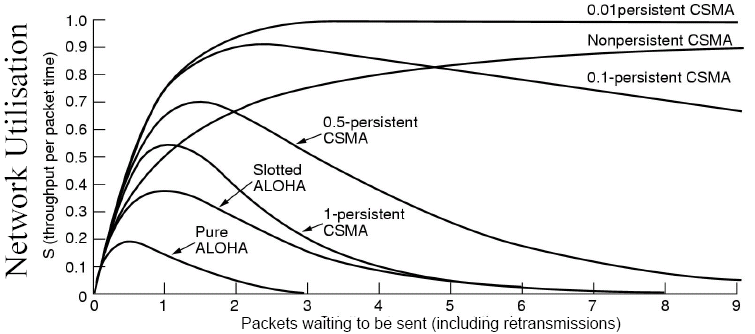
One method of solving this problem is ALOHA, which is contention system. In ALOHA, users transmit when data becomes available, however collisions are inevitable, and the colliding frames are destroyed. A sender finds out if a frame is destroyed by also listening. A variation of ALOHA called slotted ALOHA imposes agreed timeslots (this requires global time, however - see later lectures), and you only send at the start of a timeslot.
ALOHA developed into carrier sense multiple access (CSMA), where a sender listens to a channel first and only transmits if it is silent. If a collision occurs, the station waits a random amount of time and then retries. There are two different varieties of CSMA, non-persistent CSMA, which senses transmission and sends if free, but waits for re-sensing if busy, and p-persistent CSMA which senses if the channel is silent, then transmits with probability (1 - p). If the channel is not free after waiting, it continually senses until it is free.
However, we now have the problem of when is a collision detected. An improvement to CSMA can be made by aborting transmission as soon as a collision is detected (however, senders may not immediately hear the collision). The contention period here is normally quite small, as collisions can be detected in just a few microseconds. CSMA-CD also works better with large packets, as once connection is established, the throughput is greater (although this does have the disadvantage of reducing other packets' responsiveness).
Another way of solving the problem is to use collision avoidance, where it is agreed in advance when the sender has sole access to the network. Some ways of implementing this include:
- Time Division Multiplexing - have an agreed time slot for a message (this does have the requirement of global time, however)
- Frequency Division Multiplexing - frequency range of wireless communications split into bands, each user having exclusive access
- Wavelength Division Multiple Access - like FDM, but for fibre optics and at the visible area of the spectrum
- Spread Spectrum (frequency hopping) - this is used to prevent jamming, where the frequency changes according to a system only the sender and receiver know
Ethernet (IEEE802.3)
Ethernet is used as a broadcast bus, where CSMA-CD provides MAC.
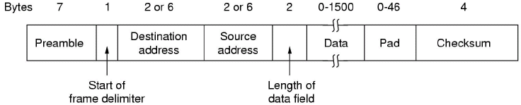
The preamble is used for hardware timing purposes (e.g., to achieve a hardware sync), and the data payload is variable (max 1.5 kb). Collisions are detected by listening on the input port whilst sending on the output port. Transmissions are aborted when a collision is detected, and retries occur after a random back-off time. Usual efficiency is about 80-90%.
The packet must be padded where the data length is less than minimum (64 bytes).
Controller Area Network
The Controller Area Network (CAN) is an advanced serial bus system that efficiently supports distributed, real-time control. It was originally developed for use in automobiles by Bosch in the late 1980s. CAN has been standardised by ISO as ISO 11898 and is now used in more than just automobiles.
It has been widely adopted as it reduces the amount of wiring required, as CAN controllers are cheap and can even be incorporated into the client itself.
The CAN protocol is only defined at the physical and datalink layers, however the exact physical states are not declared in the specification.
Data messages on the CAN bus do not contain the address of either the sender or receiver, but the content of each message is labelled by an identifier that is unique throughout the network. Messages are broadcast atomically, where they are either simultaneously accepted by all nodes, or no nodes. This identifier describes the meaning of the data, and for certain applications, the assignment of message identifiers to functions is standardised. Messages are then filtered according to their relevance; if a message is relevant, it is processed by the receiver.
The unique identifier also determines the priority of the message - the lower the value of the identifier, the higher the priority. When the bus is considered ideal, all nodes will attempt to send their current highest priority sendable message. The highest priority message is guaranteed to gain access to the bus and lower priority messages are automatically retransmitted in the next bus cycle, or in a subsequent bus cycle if there are still other, higher priority messages waiting to be sent.
CAN often uses a two wire bus, such as twisted pair, although flat pair cable performs well, it does generate more noise and is more susceptible to noise (EMI). NRZ encoding with bit stuffing is used for data communication on a differential two wire bus (i.e., each wire carries opposite signal, e.g., one +5V and another -5V). NRZ encoding ensures compact messages with a minimum number of transitions and a high resiliance to external disturbance. This allows CAN to operate in harsh and noisy environments. The ISO standard recommends that bus interface chips be designed so communication can continue even if either of the two wires in the bus is broken, or either way is shorted to power or ground.
CAN uses bit arbitration, which means that all nodes must hear data in the same cycle, which means the maximum data rate is limited by the speed of light and the cable length. CAN uses CSMA-CD, however unlike Ethernet, when frames are transmitted at the same time, non-destructive bitwise arbitration allows the highest priority message to gain bus access.
Bit arbitration works by that when the bus has been silent for long enough, each node begins to output the identifier for its highest priority message. Bus conflicts are therefore resolved by non-destructive bitwise arbitration using a wired-AND (open collector) where dominant bits (0) overwrite recessive bits (1). Nodes read as well as write to the bus, so nodes back off when it reads a value different to what it output.
CAN transmits and receives data using message frames, which carry up to 8 bytes of data from a transmitting node to the relevant receiving nodes. The end of a message is indicated by five consecutive identical bits (i.e., the bus goes silent), and bit stuffing of real data is used to avoid this combination cropping up in a data combination.
Switched Networks
Broadcast and point-to-point networks are good for message passing as they are connectionless, but they are less good for streaming applications (e.g., transmission of video/sound data streams). Switched networks are better for connection orrientated requirements, as well as many WAN applications and streaming applications.
In switched networks, all computers are directly linked to the swich (i.e., computers are not linked directly to one another), and switching is used to transmit information between two nodes which do not share a direct link.
Packet switching is worked by placing computers at each switching node. Basic processing and storage is made available, and "store and forward" networks (where packets are forwarded from source to destination when a link to the destination becomes available) are now possible. A permanent connection is established between each node and the switch, and to send a packet from A to B, the switch determines when the packet is forwarded to B. Switches can also switch between different types of physical networks.
One way of implementing switch networks is using source routing, where each packet has enough info to enable any switch to decide how to get the packet to its destination - overheads are expensive as the full route must be known beforehand and must be embedded in the packet being sent.
Another method is virtual circuit switching. VC switching is similar to a phone call, where there is an explicit setup and tear-down stage, so all packets for that connection follow the same circuit. This is sometimes called a connection-orrientated model. Each packet contains a VCI (virtual circuit ID) which is then reassigned by each switch for the next VC switch based on a VCI table. Switches here are complicated, and timing guarantees are difficult. Only the connection request needs to contain the full destination address, and as the VCI tends to be smaller than the connection address, the per-packet overhead is small.
Due to the setup time, you generally have to wait a full round trip time (RTT) for connection setup before sending the first data packet, so this is inefficient for short or bursty packets. Additionally, if a switch or link in the connection fails, the connection is broken and a new one needs to be set up.
The connection set up does provide an opportunity to reserve resources, however (this is important if Quality of Service is a prime requirement for applications)
Another method is datagram switching. Here, there is no connection set up phase and each packet is forwarded independently, so the model is completely connectionless, and is analogous to the postal system. Each switch maintains a forwarding (routing) table which maps host to port, therefore a switch needs to know which port to send a packet on to reach its desired host.
In this model, there is no RTT delay waiting for the connection setup; a host can send data as soon as it is ready. However, the source host has no way of knowing if the network is capable of delivering such a packet, or if the destination host is even up or available. However, as packets are treated independently, it is possible to route around link and node failures. Every packet must contain the full address of the destination, so the overhead per packet is higher than for the connection-orrientated model.
LANs have physical limitations, specifically in the length, so we need to introduce ways to get round this.
Hubs
Hubs act at a physical layer and are basically multi-port repeaters. They perform no routing (so are only useful in broadcast networks) and simply receive and send onwards. They can help reduce effects such as SNR, but can increase collisions. Hubs act at the physical layer and join network segments.
Bridges
Bridges act at the data-link layer and connect two or more network segments or LANs (however, they must be of the same type). They have an accept-and-forward strategy, and perform a basic level of routing. They usually do not alter a packet header.
A key issue is that we must ensure that we forward a packet to the correct LAN. The simplest way to implement this is to use fixed routing - this is where a route is assigned for all source/destination pairs, so is only usable in small networks. The selected route is usually the one with the fewest hops, but problems can be encountered if the network changes or new machines are added.
Learning bridges work by having a routing table and entries in this are learnt from the source address, and is effective if we have a tree network topology. In learning bridges, we only forward if necessary, so unnecessary traffic is not created on segments or LANs. The algorithm for learning bridges is such that when a frame arrives on a port P at the bridge, it must have come from the direction of a sending LAN, so we examine this source address S. We then update the forwarding table to reflect that to send messages to destination S, we forward it to the LAN connected to port P. Each entry in the forwarding table is then timestamped to enable entries to be deleted after a fixed time - this enables the table to reflect changes in network topology (e.g., S could move from port 1 to port 2 and the bridge would learn this next time S sends a message).
In learning bridges however, we have the problem of network loops causing messages to arrive at a bridge from multiple directions, which causes the route table to oscillate. To solve this, we can use a simple result from graph theory: "for any connected graph, consisting of nodes and edges connecting pairs of nodes, there is a spanning tree of edges that maintains the connectivity of the graph but contains no closed loops".
To implement this, we have bridges running a distributed algorithm to find a spanning tree. An attempt is made to find the best tree (with respect to number of hops), and the topology is not know before running the algorithm. The algorithm is that each bridge has a unique ID, and each port on a bridge is assigned a cost (sometimes the same cost for each port, and is usually factors such as bitrate supported by a port). The bridge with the smallest ID is the tree root. The number of hops is initiallised to 0.
The bridges then need to find the root bridge, so all bridges circulate messages containing their ID and the number of hops. When a bridge receives one of these messages, if the ID is lower than its own message, or the ID is same but has a lower cost, it adds one on to the hop count and forwards the message on, stopping sending its own message, as it has identified another bridge that could be the root, or a faster route to the root, otherwise the message is discarded. Eventually, only messages from the root bridge will be circulating, and all other bridges should have backed off as their ID/cost is higher. Loops are therefore avoided, assuming that all identifiers are unique.
Each bridge will then determine its root port (i.e., port with least cost to root) and a dedicated bridge is chosen for each LAN. Where a LAN has more than one bridge, the bridge sends messages to other (external) bridges on the same segment (this is achieved by no bridge forwarding a message to another LAN), and the message contains the cost to root for each bridge. The bridge with the smallest cost to root is then chosen as the designated bridge (i.e., fastest route from bridge up the tree chosen).
This algorithm results in that one bridge on each LAN is selected as the designated bridge, each bridge forwards frames over each LAN for which it is the designated bridge. This is still a learning-style algorithm, but there are no loops.
Bridges do have the problem of not scaling, as the spanning tree algorithm does not scale, and having a single designated bridge can be a bottleneck. Additionally, it does not accomodate heterogeneity (bridges make use of frame headers, so they can only support networks with the same format for addresses). Additionally, different MTUs can cause problems.
Switches
We can think of switches as multiport bridges.
Switches solve the problem of static network topologies dictated by attempts to minimise wiring, so switched networks provide flexible architecture for networks. Switches allow packets to traverse point-to-point WANs from source to destination, and are fundamental for WANs.
Recently, switches have also become cost effective for LANs, as they allow the ability of a local LAN to have effective total connectivity between nodes, and provide fast communication and less contention. The advantages are that whilst wiring is still based on physical demands (i.e., computer is connected to the closest switch), LANs can be configured logically (usually in software).
LAN switches are strictly switching hubs, and switch between single LAN types. They are termed level 2 switches (from the OSI model), as the inspect packets at the frame level by looking for the MAC address. They can be implemented as store-and-forward switches, where the incoming frame is buffered briefly before being routed, which allows the number of switches to be less than the number of ports (although this has a performance hit), or cut-through switches, where an incoming frame is routed as soon as the MAC address is received (usually at the front of the frame, e.g., in Ethernet). This can lead to propogation of faulty frames, as the sending frame is forwarded before the CRC is checked.
Routers
Routers are capable of providing interconnects between different sorts of LANs and WANs.
ATM
ATM stands for asynchronous transfer mode and is a connection-oriented packet-switched network. It was developed by and for the telecoms industry and was originally designed for WAN, although it is now used in LAN settings. It is a IEC standard.
ATM requires the setting up of a virtual circuit before transmission can start, and connections are identified by a two-level hierarchy consiting of a VCI (virtual circuit identifier) giving the route across switches from source to destination and a virtual path identifier which identifies a set of inter-switch routes. A combination of VCI and VPI can be thought of as a virtual circuit in packet switched network terminology.
The ATM model is a three-level model consisting of an ATM Adaption Layer (AAL) which adapts information to be sent to the cell structure (i.e., creates packets or cells for, e.g., specially dealing with voice), an ATM layer which is responsible for multiplexing and switching packets (or cells) and a physical or adaptation layer which is responsible for adapting to the underlying transmission media.
Packets in ATM are called cells and are made up of a 5-byte header and a 48-byte fixed length payload.
![]()
- GFC - generic flow control
- VPI - virtual path identifier
- VCI - virtual circuit identifier
- Type - mangement, congestion control, AAL, etc (AAL 1 and 2 for applications that need a guaranteed data rate, 3 and 4 for packet data and 5 as an alternate packet data standard)
- CLP - cell loss priority (when network is overloaded, packets of a lower priority are lost first)
- HEC - header error check
Fixed length packets are easier to switch in hardware, and enables hardware switch parallelism as variable length packets inevitably require software to process them. When deciding what length to use, there is no optimal, as small packets have a high header-to-data overhead and large packets have an underutilisation problem. Small packets do improve latency (especially important for voice), e.g., if sound is recorded at 64 kbps and a cell was 1000 bytes long, you would need to wait 125 ms before a cell was full, which is too long for voice. ATM was a compromise of Europes desired 32 bytes and Americas desired 64 bytes.
With ATM there is a problem of congestion if the rate at which things are being put into the queue for the output ports is close to or greater than the maximum data rate of the output port. Recognising congestion can take time, so it is often better to try to prevent congestion rather than react to it. Ways of avoiding congestion include:
- Admission Control - this is used to decide whether or not a request for a new connection is allowed, and once this is set up all parties have some knowledge of likely data rates along the connection
- Rate Policing - this controls flow into a network across a channel to be regular, using a "leaky-bucket" algorithm (i.e., buffer packets and release at a regular rate). This transforms a bursty data arrival into a regular drip of packets into the network, speading the load. This is usually matched to an agreed data rate set up by admission control
However, if congestion still arises in physical networks, we can use the CLP byte to shed low priority traffic.
The ATM model does not easily map on to the OSI and TCP/IP models, as ATM has characteristics of end-to-end VCs, switching and routing, which occur at OSI levels 3 and 4, but the TCP/IP view is that ATM sits at levels 1 and 2, which enables them to place IP over it, however ATM does not have the characteristics of a single hop data-link layer, and it needs messages to be split and reformed which IP does not support.
We can try and represent how ATM fits into the OSI model below, however:
| OSI Layer | ATM Layer | ATM Sublayer | Functionality |
|---|---|---|---|
| 3/4 | AAL | CS |
(TCP, UDP and IP would go between these layers) |
| SAR |
|
||
| 2/3 | ATM |
|
|
| 2 | Physical | TC |
|
| 1 | PMD |
|
Network Layer
We have a requirement to cope with internetworking, that is, when communication occurs across many (potentially) different networks. The physical and data-link layers alone can join similar networks, however we must be able to join different networks. We have to consider issues such as heterogeneity (communication may need to traverse many different networks to get to the destination) and scale, which itself has issues such as routing (how to find efficient paths through networks consisting of millions of nodes) and addressing (how to assign unique identifiers to each node).
An internetwork is an arbitrary collection of networks interconnected to provide an end-to-end service, and works by a concatentation of networks, such as Ethernet, PPP, FDDI (Fibre Distributed Data I/F), etc...
Both hosts and routers need the network layer of the stack, however routers do not consider any layers higher, which are only considered by the hosts.
A common network layer implementation is IP (Internet Protocol), which sits at level 3 in the OSI stack and at the Internet layer in the TCP/IP stack. We need to consider which host-to-host protocols IP needs to support, as well as the fact it needs to be supportable by the underlying physical network (i.e., layers 1 and 2). IP is connectionless (datagram-based) and has a best-effort delivery (unreliable service) model - packets can be lost, delivered out of order, duplicates can arrive and packets can be delayed for a very long time.
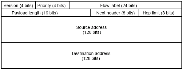
The format of a datagram packet in IPv4 looks like this:
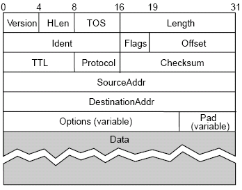
IPv4 supports a maximum data length of 65535 bytes, and allows a TOS (type of service) marker that allows different treatment of packets depending upon application needs. TTL (Time To Live) is used as a hop count; it is set by the sender and is decremented by routers and when it reaches 0, the packet is killed. In this case, the addresses are IP addresses, not raw network addresses.
Each network has some MTU (maximum transmission unit), which is the largest IP datagram that can be carried in a frame, e.g., for Ethernet this is 1500 bytes, and for ATM (CS-PDU), this is 64 kb (we are only interested in the size of the ATM packet, not an ATM cell), so the IP datagram must fit into the payload of a frame.
A strategy to implement this is to fragment when necessary (i.e., when MTU < Datagram), but we should try to avoid fragmentation at the source host (i.e., the source should not create datagrams bigger than the MTU to the first router). Refragmentation is possible en route, but as fragments are self-contained datagrams, we can delay reassembly until we reach the destination host, which could save time if the packets need disassembling again at a later point in the route. However, we can not recover from lost fragments.
When fragmenting and reassembling, we can use the offset parameter in the field to tell us how many bytes from the start of the datagram the current packet is. The first bit of the offset is set to 0 when the last packet is received so it is known when the datagram has been completely received. The ident field is used to uniquely identify a datagram, so you know which part of a packet a fragment belongs to when reassembling.
We also need to consider the problem of global addressing. All addresses must be unique within their scope (e.g., for the Internet, this must be global, but for an intranet, it only need to be within the current LAN). Addresses are hierarchial and consist of a network part and and a host part - this is essential for scalability, as we only need to consider the network when we are sending, which can then forward to the host. Routers do not need to know about all hosts, only networks.
IPv4 addresses are 32 bits long and are represented by a dot notation which groups them into 4 groups of 8 bits, e.g., 10.23.4.55, 123.66.43.4, 144.32.40.240, etc...
There are two ways of identifying the network part of a host, originally classful address space was used, but this has now moved to classless/subnetting in the modern Internet.
Classful Routing
In classful routing, there are 5 classes of addresses, named A-E, however D addresses are reserved for multicast, which is rarely used on the modern Internet and class E addresses are reserved. A class can be identified by its leading value, and classes differ by how many bits the network number and host numbers use.
| Class | Leading Value | Bit length of network number | Bit length of host number |
|---|---|---|---|
| A | 0 | 7 | 24 |
| B | 10 | 14 | 16 |
| C | 110 | 21 | 8 |
| D | 1110 | N/A | N/A |
| E | 1111 | N/A | N/A |
Choices over which class an organisation is supplied are assigned based on how many hosts are anticipated to be used in the network, and within classes, ranges were assigned geographically (e.g., 144.x for the UK, etc).
Classless Inter-Domain Routing and Subnets
The original intent of classful routing was to have the network part of an IP address would identify exactly one network. However, for every network under 255 hosts, a class C was needed, and for over 255 hosts, a class B. This can lead to a large wastage, a class C with 2 hosts is only 0.78% efficient, and a class B with 256 hosts is only 0.39% efficient. Additionally, there were still a lot of networks, and route propagation protocols do not scale well.
Subnets add another level to the address/routing hierarchy, as subnet masks are used to define a variable partition of the host part. The mask reveals the subnet number which is part of the IP address to be compared with the routing table entry, this is more flexible than classful address space, as it allows a greater break up of addresses and more efficiency.
IP uses the datagram forwarding strategy, where every datagram contains the destination address. If the node is directly connected to the destination network, we can forward directly to the host, but if it is not directly connected, then we forward to some router (the gateway/default router), which has a forwarding table that maps the network number into the next hop.
Once a message has reached the appropriate network, address translation must be used to map IP addresses into physical network addresses. ARP (Address Resolution Protocol) is used to do this. A table is maintained of IP to physical address bindings, and a request is broadcast to all nodes within the local network if an IP is not in the table. The target machine responds with its physical address, and table entries are discarded if they are not refreshed (e.g., every 10-15 minutes).
When a host or router can not process an IP datagram, and error message is returned using ICMP (Internet Control Message Protocol). Typical errors/ICMP messages include:
- Echo (ping)
- Redirect (from router to source host)
- Destination unreachable (protocol, port or host)
- TTL exceeded (so datagrams don't cycle/hop forever)
- Checksum failed
- Reassembly failed
- Can not fragment
Routing
Forwarding is selecting an output port based on the destination address and the routing table, and routing is the process by which the routing table is built.
The easiest way to represent a network for routing is as a weighted graph, and we then have the problem of finding the lowest cost path between two nodes. Factors to consider include static factors such as topology and dynamic issues such as load. A simple solution is to send the packet out on all interfaces except the one it came in on, this is guaranteed to reach the destination in the shortest time, but causes congestion, duplication, etc...
We can use metrics to measure network performance. The original ARPANET metric measured the number of packets queued on each link, and took neither latency nor bandwidth into consideration. A new ARPANET metric was developed to combat this, where each incoming packet is stamped with an arrival time (AT), and the departure time (DT) is recorded. When a link-level ACK arrives, the delay time is then computed as Delay = (DT - AT) + Transmit + Latency. If a timeout occurs, DT is reset to the time the packet was retransmitted, and the link cost is the average delay over some time period.
RIP (Routing Information Protocol) can be used to compute a distance vector. Each node contains a set of triples (Destination, Cost, NextHop), and exchanges updates with its directly connected neighbours, either periodically (typically in the order of several seconds) or whenever the table changes (called a triggered update). The updates are in a form of a list of pairs (Destination, Cost), and if a route appears to be better (i.e., have a smaller cost), the local table is updated with the new NextHop. Existing routes should be refreshed periodically, and delete if they time out.
When subnetting is used, the routing algorithm changes, however. The entries are now of the form (SubnetNumber, SubnetMask, Cost, NextHop). A binary AND is performed on the IP and the subnet mask, and then it is seen whether or not it matches the subnet number, and if it is, forwarded on to NextHop.
Problems can occur with loops and failures, however, where an out of date node publishes information about a link that goes down to NextHop, and the node decides it can reach the failed node through the out-of-date node, causing an infinite loop. To break these loops, we can do things such as set "infinity" to an arbitrary number, such as 16, or use a split horizon, where routes learnt from a neighbour are not sent back to that neighbour.
To solve the problem of extremely large routing tables, interdomain routing is used. Here, networks are parts of autonomous systems (AS), which correspond to an administrative domain. They are autonomous as what happens inside an AS doesn't affect the outside. Route propogation now uses a two-level hierarchy, with an interior gateway protocol to speak to other nodes inside the network, and an exterior gateway protocol (i.e., BGP is an Internet wide standard) to talk to neighbours (or peers) of the AS.
EGP (the exterior gateway protocol) was previously used on the Internet before being replaced by BGP (border gateway protocol). It is designed for a tree-structured Internet, and is concerned with reachability, not optimal routes. The protocol consists of messages for neighbour acquisition (one router requests that another be its peer, and peers then exchange reachability information), neighbour reachability (one router periodically tests if another if still reachable, by exchanging HELLO/ACK messages, and a k out of n rule is used) and routing updates (peers periodically exchange their distance-vector routing tables).
Constraints in routing are varied, and normally have to be programmed into routers manually.
BGP4 is the current version of the border gateway protocol used on the Internet. BGP4 has 4 AS types:
- stub AS - has a single connection to one other AS, and carries local traffic only
- multihomed AS - has connections to more than one AS but only carries local traffic; it does not allow transit between peers across its network
- transit AS - has connections to more than one AS, and carries both local and transit traffic
Each AS has one or more border routers, and one BGP speaker that advertises its local networks, other reachable networks (in the case of transit AS) and gives path information.
IPv6
IPv6 features completely classless 128-bit addresses. The address contains host "subnet" details and a specific address. It works around the fragmentation problem by using a method called "end-to-end" fragmentation, where once sent, no further fragmentation can occur, as the minimum MTU on route is determined prior to the send (either by using path discovery, or default to a minimum MTU - 1280 bytes). It provides many services such as real-time (using priority field in the header), multicast and anycast (ensuring delivery to at least one set of nodes). Security can also occur at the IP layer via authentication and an encrypted payload.
The header is 40 bytes long, with extensions (fixed order, with a mostly fixed length). The type of extensions are indicated by a "next header" field, and contain information such as routing or fragmentation information.
Currently, IPv6 is implemented on top of the current IPv4 network using a method called tunneling. Tunneling is a transmission of packets through an alien network (in this case IPv4), but where both the sender and recipient speak a common protocol. The sender encapsulates an IPv6 packet within an IPv4 packet and sends it, however fragmentation may be necessary. It is effectively a software layer.
Transport Layer
The IP/network layers provide the upper layers with data independence from the underlying switching/transmission technologies, which are used to establish, maintain and terminate connections.
The transport (or host-to-host) layer (layer 4 in the OSI model) gives a reliable, transparent transfer of data between end points and provides end-to-end error recovery and flow control, this requires:
- Guaranteed message delivery
- Messages are delivered to applications in the same order in which they are sent
- At most one copy of a message is delivered
- Arbitrarily large messages are supported
- The receiver can flow control the sender
The transport layer relies on an underlying best effort network (e.g., IP) that limits messages to some finite size, but is not perfect. The requirements of the transfer layer exist to mask the unreliability of the underlying network, that is, the transport layer basically manages the issues caused by lower level routing.
Endpoints are identified by ports, and host:port pairs provide naming in the transport layer. Servers have well known ports (see /etc/services on UNIX-based systems), which are only interpreted on a host. This allows multiplexing amonst applications for the same service - the transport layer routes a message to the correct service based on the destination port.
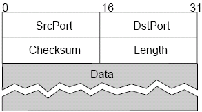
User Datagram Protocol
UDP, the user datagram protocol, is an unreliable and unordered protocol based on the datagram idea. It extends the unreliable host-to-host service to a process-to-process level, it consists of no flow control and has a simple header format, with an optional checksum.
Both UDP and IP provide a connectionless unreliable interface, and the only thing UDP offers IP is the idea of a port interface. However, UDP is service-oriented and removes the need for the sender to know much about the receiver/network topology, which hosts should not know for transparency reasons.
Transmission Control Protocol
TCP, the Transmission Control Protocol, provide a connection-oriented transport. It is full-duplex and point-to-point and has flow control, to keep the sender from overrunning the receiver, and congestion control, to keep the sender from overrunning the network.
TCP uses the concept of a reliable byte-stream. Applications read and write bytes, but TCP sends and receives segments and the translation between the two is done using buffers. It has the same port concept idea as UDP and is similar in concept to ATM.
TCP needs to address end-to-end issues, as it can potentially connect many different hosts, so explicit connection establishment and termination is required. Additionally, it must deal with problems that can be introduced at the network layer, such as potentially different round trip times (RTT), so an adaptive timeout mechanism is needed; or long delays in the network, so we need to be able to handle the arrival of very old packets; or different capacity at the destination compared to the source or on the network, so we need to be able to deal with congestion and capacity issues.

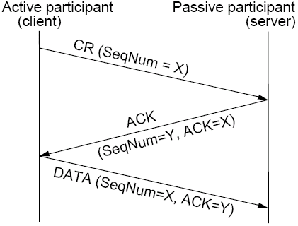
Connections in TCP are established by a three way handshake. Initially, a server is listening for client connection requests (CR), then, when a client issues a CR, then the server checks if a server is listening on the selected port and sends an ACK if it is. The ACK indicates next data is expected, so the client acknowledges the connection and synchronises sequence numbers in the first data segment that is sent out.
The TCP model has a state diagram which indicates which particular state the communication is in at any one time. In addition to opening the connection, connections are ended by either end sending a segment with the FIN bit set in the header.

TCP considers flow control, which is important as both senders and receivers have a finite buffer space, and they process data at different rates. A sliding window protocol is used to provide flow control. Here, a time window of connections can be established and messages sent. It is possible to deal with out-of-order arrival of segments and to have multiple outstanding (un-ACKed) segments in the time window. The upper bound of un-ACKed segments sets the window size, and this limits the amount of buffer space required at the sender and receiver. Having a bigger window gives us more flexibility, but increases the risk of more failures remaining undetected.
Flow control is implemented on the sender to bound failure detection, i.e., where a message is not acknowledged sufficiently quick enough. A sequence number is assigned to each frame, and three state variables are maintained - SWS (send window size), which is the maximum number of unacknowledged frames the sender can transmit, LAR, the sequence number of the last acknowledgement received and LFS, the sequence number of the last frame sent. We must then maintain the invariant LFS - LAR ≤ SWS.
When an ACK arrives, we advance the LAR pointer, but we must retransmit the frame if an ACK is not received within a given time. As we need to buffer up to SWS frames, this means the transmission failure detection time is bounded.
To support out-of-order receives and reject out-of-date messages, the receiver must also implement flow control. Here, three state variables are maintained, the receive window size (RWS), the largest frame acceptable (LFA - basically, how many messages make up the largest allowed frame), and LFR, the last frame received, but not delivered. An invariant LFA - LFR ≤ RWS must be maintained.
When a frame with sequence number S arrives, if LFR < S ≤ LFA, then we accept, else if S ≤ LFR or S > LFA, we discard. Cumulative ACKs are sent, e.g., if we receive segments in the order 7, 8, 6, then we wait until 6 arrives before acknowledging 7 and 8. The LFA does define a limit, however, e.g., if 11 is received before any other packets, then it may be rejected. The buffer supports up to RFS frames.
Flow control allows us to deal with errors. e.g., if RWS = 1, then after an error, subsequent frames are discarded, so the sender must go back N frames and repeat them. N is decided mainly by network delay. If RWS > 1, then after an error, subsequent frames are buffered, and the sender selectively repeats the missed frame. This is a trade off between bandwidth required and the buffer space required, and typically, the larger the transmission delay and likely errors, the larger the buffer that is needed.
Sliding window and flow control is implemented in TCP using the Acknowledgement, SequenceNum, AdvertisedWindow and Flags fields. The AdvertisedWindow field in the header defines the window to be used for transmission.
ACK messages consist of the acknowledged sequence number in the Acknowledgement field, and in the same message, a new AdvertisedWindow can be sent. The AdvertisedWindow tells us how many more bytes can be sent than those already received/acknowledged.
A problem with TCP is that of a 32-bit sequence number, which is limited given current network speeds, and it is only a matter of seconds in gigabit networks until sequence numbers start to repeat. We need to ensure that the network is well utilised, which has implications on window size. A 16-bit AdvertisedWindow means we only have 64 kbytes before wraparound. To work round this, TCP has been given the option of a scaling factor to cope.
A final problem to consider in TCP is that of retransmission (from the sender) of unacknowledged segments after some timeout has expired. This requires a timer, but there is the problem of knowing which value to use. A fixed value needs knowledge of network behaviour and does not respond to changing network conditions - too small and the network is flooded with retransmission, and two large and the receiver will stall. Another method is using an adaptive timer, however it is still difficult to monitor RTT with cumulative acknowledgements, and network conditions may change faster than we can adapt.
Adaptive retransmission does still tend to be used, however. One method involves using a weighted average, where a SampleRTT is measured for each segment/ACK pair, and a weighted average (basically a balance between actual and expected RTT) is computed: EstRTTt + 1 = α × EstRTTt + β × SampleRTT, where α + β = 1. Typically, 0.8 < α < 0.9 and 0.1 < β < 0.2. Timeout is then set based on this RTT, and is typically twice the value.
This weighted average gives quite a large timeout when the network is relatively stable, however. Another solution is the Jacobson/Karel algorithm, where the mean deviation of actual RTTs from the estimated RTTs is used.
Diff = SampleRTT - EstRTT
EstRTT = EstRTT + (δ × Diff)
Dev = Dev + δ (|Diff| - Dev)
Where δ is a factor between 0 and 1.
Variance is then considered when setting a timeout value: Timeout = μ × EstRTT + φ × Dev, where μ = 1 and φ = 4.
This algorithm is only as good as the granuality of the clock (500 ms on UNIX), and μ, φ and δ are used to control the speed of response and the ability to adapt.
The Karn/Partridge algorithm tells us not to sample the RTT when we retransmit, as the subsequent ACK may be from the original transmission, just late, so the timeout value becomes distorted. In this algorithm, the timeout is multiplied by a constant after each retransmission (often 2), which progressively gives the network longer to get a message through. When an ACK is received for a segment that has not been retransmitted, Jacobson's algorithm is used to set a timeout.
Name Services
Distributed systems often use names to refer to different resources (computers, services, remote objects, files, devices, etc). A consistent naming of resources is necessary for distributed systems - you need to be able to refer to the same resource consistently from different places in the system over a period of time. Additionally, name conflicts need to be avoided and attributes may be used to infer a name, so attributes of a required service may be enough to name a server that needs to be contacted.
Naming is an issue at each level of the OSI and TCP/IP protocol stacks. It provides an abstraction from the underlying technology, e.g., physical address at data link layer, IP address at network layer, host:port tuple at transport layer.
A name is resolved when it is mapped to the named entity - this mapping is termed a binding, and it identifies an IP address, a type of resource and other entity specific attributes (e.g., the length of time a mapping will remain valid).
Names require nested resolution - a web URL may be mapped to an IP:port tuple, which is then mapped to a physical address when it reahes the correct physical network, and then the file name part of the URL is mapped to file blocks by the file system. Each layer must be able to cope with mappings that change, however.
Name Spaces
This bit is wrong, but is
what the lecture slides
say, so use it for the exam.
URLs (uniform resource locators) are direct links to host and IPs (e.g., pisa.cs.york.ac.uk) and can scale to a limitless set of web resources. It does have the problem of web dangling references, however - if a resource moves, the URL is invalid.
URNs (uniform resource names) solve the dangling link problem, as URNs persist, even if the resource moves. The resource owner registers it with a URN lookup service, which provides the current URL when asked - if a URL changes, the owner must inform the URN lookup service. URNs identify a namespace and a resource, e.g., urn:cs.york.ac.uk/RT2001-2 identifies the resource RT2001-2 in the namespace cs.york.ac.uk. URNs also identify a scheme, e.g., http, ftp, etc...
A name space is a collection of all valid names in a given context, e.g., for a file system, the context might be a directory and the valid names are strings that follow a certain pattern (e.g., printable characters no longer than 255 characters). A valid name does not necessarily map to an existing entity (e.g., a file with a given name may not necessarily exist in that directory).
Flat name spaces (i.e., where everything is in a single context) are usually finite, but hierarchial namespaces are possibly infinite by allowing recursive contexts.
Aliases also allow greater transparency - www.cs.york.ac.uk maps to pisa.cs.york.ac.uk, but the web server can be moved to turin.cs.york.ac.uk earily if need be, as only the mapping inside the cs.york.ac.uk network needs to be changed.
Name Resolutions
Name resolution is an iterative process used to map names to primitive attributes, or to derive a name to be passed on to another name service (e.g., an aliased name may first be translated to another name, then to a reference for the actual resource). Aliases can lead to circularities, so it is often necessary to implement around cyclic lookups.
The name service for a large number of names should not be stored on a single computer, as this is a bottleneck as well as a single point of failure.
Partitioning of a name service requires a structure so that names can be resolved efficiently. This process of finding naming data within the split name service is called navigation. In iterative navigation, a client nameserver presents a name to NS1, which will resolve all or part of a name, and suggests that a further nameserver can help, if required.
To resolve a name in the DNS, e.g., milan.cs.york.ac.uk, we first contact the root nameservers which gives the address of the nameserver for .uk, which in turn gives us the address for the nameserver for .ac.uk, which gives us the main York nameserver for york.ac.uk, which we can ask for the cs.york.ac.uk nameserver, which will finally give us the address of milan.
This co-ordinated resolution can involve recursive or non-recursive navigation. This is the opposite to iterative navigation, which is client controlled, but this is server controlled. In non-recursive, the root nameserver does all of the lookups, whereas in a recursive setup, each server contacts the upstream servers and passes the results back.
The DNS name space is partitioned organisationally and geographically, e.g., milan.cs.york.ac.uk identifies the server milan in the Computer Science department of the University of York, which is an academic institution in the UK. Components are seperated by dots and it is case-insensitive.
DNS supports host name resolution (A records for IPv4 and AAAA records for IPv6), mail host locations (MX records), aliases (CNAME records), reverse lookups (IPs to hostnames with PTR records), etc, and typically uses the iterative lookup mechanism.
Most DNS servers use caching to increase performance, which helps in availability of name service data if a nameserver crashes. DNS records are accompanied by a TTL (time to live), which tells the cache how long to cache the record for before refreshing. We call responses from caches to be "non-authorative", as they may not be accurate and are out-of-date. An authorative server is the name server that actually manages the zone records for that domain name, and this server needs to intelligently manage the TTL to balance between load and accuracy.
DNS clients are called resolvers and are often implemented in the OS as a library function.
Services Discovery
Software such as Jini provides facilities for service discovery, and are called lookup services. Lookup services allow servers to register the services they provide, and then clients query the lookup service for the required service. Infrastructure then provides an appropriate interface to a server via remote method invocation (RMI).
Lookup services should also be able to control the services that different users (e.g., visitors) can access.
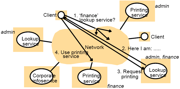
In the above example, a client requires a lookup service in the finance group, so it sends out a broadcast, to which the lookup service for that group responds. The client then communicates with the lookup to request printing. As only one printing service is registered for the finance group, the address of it is given to the client for direct communication to the printing service.
Distributed Systems
No agreement has been reached on the exact definition of a distributed system, although some definitions include:
- Tanenbaum - "A distributed system is a collection of independent computers that appears to its' users as a single coherent system"
- Coulouris et. al - A distributed system is "one in which hardware or software components located at networked computers communicate and co-ordinate their actions by passing messages"
- Lamport: "A distributed system is one that stops you getting any work done when a machine you've never even heard of crashes"
Enslow has produced a means of categorising distributed systems:
- Concurrency (or parallelism) - concurrent program execution is normal, and control and co-ordination of concurrent access to resources is important
- No global time - co-operation between programs on different computers is via message passing. Whilst close co-ordination demands a shared idea of time between computers, there are limits to accuracy of clock synchronisation achievable
- Independent failures - computers, networks and resources in distributed systems can fail independently leading to network partitioning
Challenges of Distributed Systems
Heterogeneity - Networks require standard communications protocols, hardware may vary (data types, e.g., length of an int may be implemented differently or big endian vs. little endian), OSs may provide varying implementations of network protocols and programming languages may not be implemented on some architectures (common languages e.g., Java and C tend to be used).
Openness - This determines whether or not the system can be extended or partially re-implemented. Open distributed systems enable new services (by adding new hardware and software) to be added for use by clients. Documentation of the interfaces is required for this. It is hard to design and support a system if you have little knowledge or control over how it is used or modified.
Security - Many services have high value to users. Often, secure data is passed across public networks. There is a need to ensure the concealment of the content of messages and that the identity of the client can be determined by the server (and vice versa). Common security problems include denial-of-service attacks and the security of mobile code.
Scalability - Requires that the system is still usable if many more computers/resources/services are added. Scalability requires the system to control the cost of physical resources, control performance loss, prevent software resources running out and to avoid performance bottlenecks.
Failure handling - Network partitions and computer systems fail producing incorrect, or no results. You need to detect, mask, tolerate and recover from failures. Requirements can include Mean Time Between Failures (MTBF), availability and amount of unscheduled maintenance.
Concurrency - Services and applications provide resources that are shared in distributed systems, hence shared resources can be accessed simultaneously. Operations must be synchronised to maintain data consistency.
Transparency - Concealment from the users and applications of seperation of componenets of a distributed system. We can consider different forms of transparency.
| Transparency | Description |
|---|---|
| Access | Hide differences in data representation and how a resource is accessed (network transparency) |
| Location | Hide where a resource is located (network transparency) |
| Migration | Hide that a resource may move to another location (distribution transparency) |
| Relocation | Hide that a resource may be moved to another location whilst in use (distribution transparency) |
| Replication | Hide that a service may be replicated for fault tolerance and performance (distribution transparency) |
| Concurrency | Hide that a resource may be shared by several competitive users (distribution transparency) |
| Failure | Hide the failure and recovery of a resource (distribution transparency) |
| Persistence | Hide whether a software resource is in memory or on disk (distribution transparency) |
Distributed File Systems
One of the key motivations for distributed systems is the sharing of information. Information on the Internet can be shared by the web using HTTP and browsers, however information sharing in LANs tends to have more specific requirements, such as persistent storage, distributed access to consistent data, and this isn't met by the Internet (no guaranteed consistency).
Distributed file systems provide the functionality of a non-distributed file system for clients on a distributed platform.
See File Systems
in OPS.
Like standard file systems, the user requirements for distributed file systems are:
- be able to create, delete, read and modify files
- controlled access to other users' files
- move data between files
- back up and recover the user's files in case of damage
- file access via symbolic names
The objectives of a distributed file system are:
- meet the data management needs of the user
- guarantee that the data in the file is valid
- minimise potential for lost or destroyed data
- provide performance similar to local file systems (often requires caching)
- provide reliability similar to local file systems (replication may be required)
- concurrent file updates (similar concerns to a local file system)
The distributed file system must provide a number of functions, such as the ability to locate and identify a selected file, to organise files into a structure (directories, etc) and to provide mechanisms for protection.
To acheive these objectives, we require transparency:
- access transparency (uniform API, ideally identical to the local file system)
- location transparency (uniform namespace from all clients, remote files should have a similar naming scheme to local ones)
- migration transparency (no indication of location in the file name)
- scalability (no bound on the size of the file system)
Distributed file systems typically have a directory service and a flat file service that both export RPC interfaces to the client providing access to files.
The flat file service performs operations on files on the server side. All files are identified by a UFID (unique file ID) - a flat, non-heirarchical, naming scheme (i.e., an exposed interface). This maintains a single level, flat directory to map the UFID to a file location (which also maintains a file map of logical block number to physical block address), and provides read, write, create and provides get/set attribute functions. Compared with the UNIX file service, the flat file service has no open/close operations (just quote the UFID), and to read/write, an explicit location in the file (no seek is required) is all that is needed. Operations (except create) leave the UFID unchanged.
The directory service provides a mapping between paths and names and UFIDs. It provides some directory functionality (e.g., create/delete directories to get file handles for sub-directories) and allows server-side files to appear and be manipulated in a hierarchial fashion by the client. It also defines lookup operations on the elements of the path or the filename. The lookup operation takes a UFID for a directory and a text string and returns the UFID of the file corresponding to the string. The client module recursively calls a lookup on the pathname elements (similar to an iterative nameserver). Sequential accesses can be sped up using previously resolved information.
The client module integrates and extends the flat file service and directory service under a single API. The API is usable by local applications, and can represent most forms of file systems, including UNIX hierarchial trees. It also manages information about the network location of flat file and directory service processes.
Caching
Performing all file operations on a remote server increases network traffic and decreases performance because of network delays, so recently used data or directories is cached locally for repeated access. The size of a cache unit is normally the same as the block unit for transfers, and as larger block sizes means lower network overheads.
The cache location is either on the client or the server. If we cache on the client size, local disc tends to be non-volative and have a large size and main memory is faster, smaller but volatile, however they are both difficult to maintain consistency for writes whilst having a low network load. However, if we cache on the server side, in memory there is faster I/O, no consistency problems, more memory is typically available than in a client, but it is volatile and network load increases.
It is difficult to maintain file consistency when caching, and there are three cache flush policies, write through to server (information is written to the cache and server in parallel, which is reliable, but has poor write performance), delayed write (periodically, or when cached block is discarded by the cache replacement algorithm, multiple blocks are bulk written, but there is ambiguity for other file readers) and write on close (but there is a problem if files are open for a long term). The choice depends in importance of consistency and usage patterns.
Sun NFS
The Sun NFS is the most famous implementation of a network file system and consists of a collection of protocols that provide clients with a model of a distributed file system and is based upon RPC. It provides one-copy semantics for consistency, where updates are written to the single copy and are available immediately, and is similar to a local file system, based on the concept of delegation. It does have to cope with network, server and client failures.
Access to the servers files is via the NFS server and the flat file server. The virtual file system helps map to actual UNIX file system. The NFS allows transparent access to the remote filesystem, where the server exports all or part of a filesystem, and the client mounts all or part of it into the clients filesystem.
Name resolution becomes iterative, which increases network traffic. In some ways, it would be better to have recursive name resolution, but this has a higher load on the server.
NFS implements server-side caching with read-ahead and write-behind caching in the main memory. Client-side caching works by each client having a memory cache containing data previously read from a file, and the server may delegate some rights to a client. This delegation may be recalled if another machine contacts the server to access the file. The server must keep track of which file it has delegated, and to whom.
Cache validation checks whether the client copy is still valid (e.g., whether or not the TTL has expired), or whether the server copy been updated. This is quicker than updating the file. Modification and validation timestamps are used, along with a freshness interval, which is set adaptively, depending on frequency of file updates. This could be 3-30 seconds for files, or 30-60 seconds for directories.
Synchronisation of files is difficult in distributed file systems if caching is used. To solve this, we have multiple options, such as propogating all changes to server immediately (which is inefficient), or using session semantics (changes to open files visible to the modifying process immediately, and only when the file is closed are changes made available to others. NFS adopts session semantics so consistency could be a problem. Concurrent access to files does remain a problem, and issues include preventing more than one simultaneously attempt to write to a file, so file locks can be used.
NFS was developed on SunRPC, which uses at-least-once semantics, so NFS implements a duplicate-request cache, so each RPC contains a unique identifier which is cached. If a call is still in progress when a duplicate request arrives, it is ignored, which gives a combination similar to at-most-once semantics. The difference is the acknowledgement the client has when the result has been received.
File locks can be used, which allow one writer and multiple concurrent readers. To lock a file, special lock commands can be used. However, we need to consider what happens if a client crashes whilst holding a lock, so the server issues a lease on each lock, and when it expires the lock is removed automatically by the server. A renew() command exists which requests that the lock is renewed. However, if the server crashes, the server will probably lose information on locks granted to files, but when it reboots, the server will enter a grace period where clients can reclaim locks previously granted. During the grace period, only claims for previous locks will be accepted - i.e., no new locks. The leasing approach does require the client and the server to have reasonably synchronised clocks.
Delegation also causes problems when a failure occurs and a cache isn't written back - full recovery is impossible, unless the cache is persistent. The NFS places responsibility on the client for providing file recovery (which is very difficult). If the server crashes, delegations are allowed to be reclaimed during the grace period. In general, mechanisms used for caching are highly dependent of the needs of the system and future characteristics.
We can compare the criteria for distributed file systems to Sun NFS:
- Access Transparency - The UNIX API provides the same interface as the VFS
- Location Transparency - NFS does not enforce a network-wide namespace. Therefore, different machines may mount different combinations of remote filesystems.
- Migration transparency - Not fully achieved in NFS as mount tables must change if file changes filesystem
- Scalability - Yes
- File Replication - Not supported
- Fault Tolerance - Similar to local files, but some differences due to distribution
- Consistency - One-copy semantics
Mobile Systems
Mobility is becoming increasingly important in the world of networking and distributed systems for both interaction and connection. It is also important to stay connected whilst moving (e.g., a laptop moving between WLAN segments).
We can consider mobile systems to be stand alone devices that are able to move at the physical level, and thus require wireless communications. At the network level we want to move and maintain a network connection (mobility transparency). At the application level, code and data can move, so we need to have dynamic download of code as the application needs it, and we also need to consider mobile agents which "travel" around the network which introduces security concerns.
Mobility has an impact on the OSI and TCP/IP stacks. Previously, we have assumed that hosts connect and remain at fixed points in the network, so now we have to consider fragmentation and reassembly between layers, and naming and routing at each layer. Naming involves using both network indepdendent IP addresses and physical, network depedent addresses and routing happens by considering IP datagrams that are routed across networks by routers and then using bridges and switches to route within the physical network.
Wireless communication can range from very simple ad-hoc networks, where lots of low-resource devices work together to a more complex structured network, which have been standardised by some body (normally the IEEE). Some wireless communication standards include:
IrDA
IrDA is an infrared based standard started in 1993 based upon that used by TV remote controls. It is of limited range and of line of sight only.
The standard provides a data link layer, which is essentially a wireless serial link ranging in speed from 9600 bps to 4 Mbps. The key motivation behind IrDA was to "provide a low-cost, low-power, half-duplex, serial data interconnection standard that supports a walk-up, point-to-point user model that is adaptable to a wide range of applications and devices" - that is, it provides a convenient wireless point-to-point link. Many protocols are available to run on IrDA.
Bluetooth
Bluetooth is meant to unite the worlds of computers and telecoms. It is based in the ISM 2.4 GHz RF band with ranges from 10-100 m. It defines its own protocol stack which doesn't map on to either the OSI nor TCP/IP model. It can cope with devices moving in and out of range by broadcasting periodic "I am here" messages to establish neighbours.
Non-standard protocols need to be used to access a LAN, and Bluetooth is often not standardised across multiple manufacturers, and problems can occur implementing it.
Wireless Ethernet
The wireless Ethernet standard is defined in IEEE 802.11a, b and g, with a and b being incompatible, but g is backwards compatible with b. In IEEE 802.11b, devices can communicate at up to 11 Mbps over distances of up to 150 m and can communicate both in an ad-hoc/peer-to-peer system directly with other devices or in a more structured way with an access point.
Wireless Ethernet differs from standard IEEE 802.3 Ethernet in the implemenation of MAC and the CSMA/CS mechanism. There are still equal opportunities for all to transmit, but the MAC controls use of the transmission channel, with both added security (WEP/WPA) and slot conditions. Additionally, a fairly consistent signal strength is required through the network to detect interference and collisions (i.e., another sender), and there are more failure conditions than in wired LANs.
Hidden stations are when a failure to detect that another station is transmitting occurs. Additional problems include fading as a signal may not be heard by all nodes in the network, but is by the base station. Additionally, collision masking is not effective in wireless, as multiple transmitters may produce garbled messages. As the frequency band used by wireless Ethernet is ISM, it is shared with devices such as Bluetooth and microwave ovens so interference can occur.
MAC is augmented by slot reservation. Before sending, the receiver agrees a transmission slot and when you are ready to transmit, you sense the medium, and if there is no signal, then the medium is either available, or there are out of range stations requesting a slot, or using previously reserved slots. To request a slot, the sender sends a request to send (RTS) packet with the duration, and the receiver acknowledges this with a clear to send (CTS) packet with the duration. All stations in the range of the sender and receiver therefore know about the slot, and the sender can send with a minimal risk of collision.
This gives us a mechanism called CSMA/CA (collision avoidance), but there are still problems with nodes moving.
Mobile IP
Many devices connect at different locations so do not want a static IP address allocated. DHCP (Dynamic Host Configuration Protocol) enables a temporary IP address to be acquired, but there are still difficulties if you want to stay connected whilst moving between networks.
IP routing is based on subnets at fixed locations, however mobile IP is based on the idea of an allocation of an address in the "home" domain. When the hosts move, routing becomes more complex. A home agent (HA) in the home domain and a foreign agent (FA) in the current domain perform routing. The home domain currently routes for the sender and the foreign domain takes over hosting sender.
When a mobile host arrives at a new site, it informs the foreign agent and a temporary "care-of" address is allocated. The FA then contacts the HA of the host with the new "care-of" address. The sender communicates with the HA initially and then it is told the "care-of" address. "Care-of" addresses do timeout.
In the router of the HA, a mobility binding table is maintained on the home agent of the mobile node, and the mobile nodes home address is mapped to its current care-of address along with a lifetime. The FAs maintain a visitor list which maps the home address and HA address to the MAC address, along with the lifetime.
HAs then use IP tunneling and encapsulate all packets addressed to the mobile node and forward them to the FA. The FAs then decapsulate all packets addressed to them and forwards them to the correct node using the hardware lookup table. Mobile nodes can often perform FA functions if it receives an IP address (e.g., via DHCP). Bidirectional communications will require tunneling in each direction - this is analogous to IPv6 over IPv4 networks.
Mobile IP implements security using authentication. All parties can authenticate, but the bare minimum is that between the mobile node and the HA. Authentication uses MD5 (a 128-bit digest of the message) for added security. To protect against replay attacks, timestamps are mandatory, and sequence numbers must be unique. Unique random numbers are also generated in requests to join network that must be returned in the reply. The HA and FA do not need to share any security information.
Mobile IP has the problem of using suboptimal triangle routing, where if the mobile node is in the same sub-network as the node in which it is communicating, it could be very slow to route via the HA. It would be an improvement if packets can be directly routed. To do this, foreign agents let the corresponding node know the care-of address of the mobile node, and the corresponding node can create its own tunnel to the mobile node. This does require special software, however. The HA must initiate it with the corresponding node via a "binding update", and binding tables can become stale.
Other problems with mobile IP include redundancy problems (single HAs are fragile - so we have multiple), and frequent reports to the HA if the mobile node is moving, of which a possible solution is to cluster FAs. Security is also always a concern when data travels over untrusted networks.
IPv6 implements mobile IP in the standard, so FAs are not needed; whereas mobile IPv4 is a set of extensions that must be supported by all nodes to work. With mobile IPv6, mobile nodes can function in any location without the services of a special router as IPv6 uses stateless address auto-configuration, that is, DHCP. Home agents do still need to be told by the mobile node where it is. Additionally, with security, nodes are expected to employ strong authentication and encryption.
Voice over IP
Originally, data and phone networks were seperate each having different requirements. As networks grew, a greater need to carry data over telecom networks developed and the issue was how to carry data over telecoms networks. Currently, data is the majority of telecom traffic, so new telecoms networks being installed are data networks, and the issue shifts to being how to carry voice over data networks - the solution being to encode voice as data.
VoIP has many issues to be considered, such as user location, setting up a connection and real-time and QoS (quality of service) issues. Provision of QoS is difficult, as it is difficult to map the users' view of quality into the network stack - arguably no layers implement QoS, although some may provide a higher quality service. QoS is difficult to achieve with a limited network capacity, and all parts of the network must cooperate to provide QoS.
An implementation of VoIP is SIP - session initiation protocol, which provides a general means of negotiating a connection. SIP URLs act as locators, and users register with a local server, which permeates outwards to location servers and proxy servers so that callers can be routed to the correct hosts. Proxies then communicate together and route data onwards; however they must keep an up-to-date cache of these locations to do this.
The actual transmission protocol used is RTP for the message data (i.e., the voice) which has some QoS. RTP is a transport layer running on top of UDP. RTP headers include timing information which allows applications to specify acceptable loss rates and react accordingly, e.g., change encoding rate to reduce traffic.
RTP does rely on a network that is capable of delivering packets on time, and to maintain timeliness, we degrade the quality delivered. Networks are generally poor at delivering packets on time, so prioritisation ("traffic shaping") and reservation of bandwidth are usual methods for dealing with the problem (e.g., ATM). Variability in communication times can be significant and hence cause problems.
Both SIP and mobile IP have some similar functions: SIP provides personal mobility (SIP URLs are personal, e.g., sip:cjn503@student.cs.york.ac.uk), and mobile IP provides terminal mobility (the ability to move devices between networks). Both SIP and mobile IP are important, and it remains to be seen how they evolve together.
Time and Clock Synchronisation
One of the characteristics for distributed systems includes a lack of global time, that is, it is difficult for two machines to agree what the current time is.
Time is often required to measure delays between distributed components, synchronise streams (e.g., sound and vision), detect event ordering for casual analysis, and many utilities and applications use timestamps (e.g., in SSL).
Most machines have an idea of local time, where inaccuracies don't matter if the time is only used locally. Most local time services are implemented using a quartz clock that oscillates and decrements a counter. When the counter reaches zero, this triggers an interrupt and the counter is reset, so the interrupt rate is set to the value the counter is set to. An interrupt handler then updates a software clock, which the OS provides access to.
At any instance in a distributed system, however, independent clocks from a number of machines will be different (even if they were synchronised initially), due to crystal frequencies having a natural drift with temperature. This difference in readings is called clock skew, and a typical rate is 1 in 10-6, or 1 second in 11.6 days.
Universal Coordinated Time
Wikipedia article on
the MSF time signal
The key time source is universal co-ordinated time (UTC), which is based on atomic clocks, but leap seconds are inserted to keep in phase with astronomic time. Radio stations (MSF in the UK) broadcast UTC as an encoded time signal. Atmospheric disturbances mean that land-based UTC sources have an accuracy of ± 10 msec. GEOS (Geostationary Environment Operation Satellite) or GPS signals provide UTC to ± 0.5 msec. To support these type of services, radio or GPS receivers are required on the machine to receive the signals.
Clocks can either by synchronised internally or externally. External synchronisation is when the time source is outside of the distributed system, within some bound D, and internal synchronisation is when clocks are synchronised relative to each other. However, this does not mean they are necessarily correctly synchronised to a universal time source, just to each other.
Synchronous Systems
Synchronous systems have bounds known for the clock drift rate, maximum message transmission delay, and to execute each step of a process. In theory, the process sends a message at local time t, and the receiver gets the message at time t + T, where T is the time to send a message. The two clocks are now synchronised.
However, T is very difficult to know, but we can assume a maximum and a minimum. If we set the clock to t + min or t + max, then skew can be up to u, where u = (max - min). If we set the clock to t + (max-min)/2, then skew is up to u/2. The best skew is u(1 - 1/N), for synchronising N clocks.
Asynchronous Systems
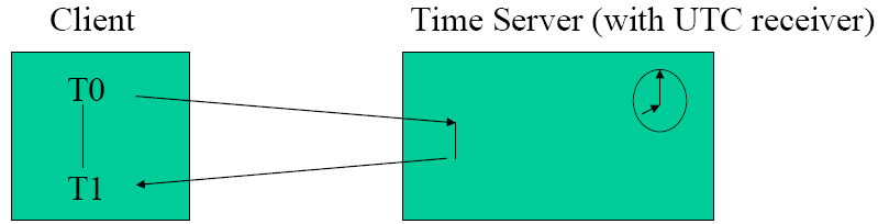
In asynchronous systems, there is no max message delay, and round-trip times between pairs of processes is often short. Cristian's algorithm tells us to estimate message propogation time p = (T1 - T0)/2, so the clock gets sent to UTC + p. To increase the accuracy of this, we can measure T1 - T0 over a number of transactions, but discard any that are over a threshold as being subject to excessive delay, or take the minimum values as the most accurate.
Here, we have the problem of the time server being a single point of failure, and a bottleneck, and spurious time server values. It also makes the assumption that the server replies instantly, and tranmission in both directions takes the same time.
The Berkeley Algorithm was developed for Berkeley UNIX (now BSD). A co-ordinator is chosen as the master, and slaves are periodically polled to query clocks. The master than estimates local times with a compensation for propogation delay. An average time is now calculated, ignoring obviously invalid times. A message is then sent to each slave indicating clock adjustment. Here, synchronisation is feasible to within 20-25 msec for 15 computers with a drift rate of 2 × 10⁻⁵ and a round trip delay of 10 msec.
Network Time Protocol
Cristian's and the Berkeley algorithms were designed for use in LANs. Synchronisation across the Internet is more problematic. The Network Time Protocol (NTP) was created with the following design aims:
- To provide a service enabling clients across the Internet to be synchronised accurately to UTP
- Provide a reliable service that can survive lengthy losses of connectivity
- Enable clients to resynchronise sufficiently frequently to offset the drift rates found in most computers
- Provide protection against interference with the time service, whether malicious or accidental
NTP is implemented with multiple time servers across the Internet. Primary servers (stratum 1) are connected directly to UTC receivers, and secondary servers (stratum 2) synchronise with the primaries. Lower stratum servers synchronise with the higher strata, where each level is less accurate than the last.
NTP scales easily to large numbers of servers and clients, and can easily cope with failures of servers (if a primary UTC server fails, it becomes a secondary).
There are different types of synchronisation modes for NTP: multicast, where 1 or more servers periodically multicast to other servers on a high-speed LAN, this sets clocks assuming some small delay and isn't very accurate; procedure call mode is similar to Cristian's algorithm, where a client requests time from a few other servers, and this is used where there is no multicast, or higher accuracy is needed; and the symmetric protocol, which is used by master servers on LANs, and the layers closest to the primaries, which is very high accuracy and is based on pairwise synchronisation.
If we do discover that our clock is fast, we can't run it backwards without weird things happening, however. The normal solution is to run it slow (e.g., interrupts are generated every 10ms, so only 9ms is added to the clock) for some period to allow normal time to catch up.
Coordination
Concurrent processes in a distributed system need to coordinate actions to maintain the illusion of the distributed system as one machine.
We can make the assumption here that processes are connected via reliable channels (eventually, all sent messages are received). If failures do occur, then these are masked by the underlying reliable communication protocols. We can also assume that alternative routes for messages in a network exist, so there is no single point of failure within the network.
Clocks that are internally synchronised are termed logical clocks. Internal synchronisation is often useful as it is more realistic to implement, and the order in which events occur is more important than the actual time which it occured.
Happens-before
This can be characterised with Lamport's happens-before relation: a → b, where event a happens before event b. If a and b are from the same process, and a occurs before b, then a → b is true. If a is the event of a message send by one process and b is the event of the same message being received by another process, then a → b is also true.
Happens-before is a transitive relationship, and concurrent events have no relation (if a and b occur at the same time in process that do not exchange messages (even indirectly), then neither a → b nor b → a is true.
To assert a happens-before relationship, timestamps are needed on events. All processes in the distributed system must agree on the time for the event, so a method is needed that copes with (logical) clocks running at different speeds on different machines.
One of the common methods of implementation is for Li (the logical clock on process i) is incremented before each event issued by Pi. When Pi sends a message m, it adds a tail Li forming a tuple (m, Li). When receiving a message (m, t), Pj computes Lj = max(Li, Lj) and then sends a receive message to the originating process with the new timestamp.
Given that different events could be given identical timestamps, a total ordering can be achieved by assigning each process a unique ID.
Often to implement consistency in a replicated distributed system, we can use totally ordered multicasts. Totally ordered multicasts are implemented by acknowledging messages (other methods exist, but this is the simplest way). Everyone in the system sees every message and every acknowledgement - this is obviously a large overhead, but is less than recreating an out-of-sync replicated database (for example). We can implement this along with the unique IDs above to create the total ordering.
Mutual Exclusion
See OPS.
Like in independent systems, distributed systems also have to share resources, which are often encapsulated in critical sections. There are two essential requirements for mutual exclusion:
- Safety - At most one process can be in a critical section at a time
- Liveness - Requests to enter/exit the critical section will eventually succeed
The second requirement implies freedom from deadlock (discussed in OPS) and starvation (freedom from which requires fairness when selecting who should receive the critical section next amongst waiting processes).
One way of implementing this is using a central server which controls access to resources and grants permissions to enter and exit critical sections. This is a simple method, but has a single point of failure.
Another way is using a token ring to form a logical token ring amongst processes. A token is given to process 0, which then circulates. When a process has a token, it can enter a critical section, perform the requested operations and then exit the critical section then handing on the token. Problems can occur if the token is lost, though - there's no way to tell if it was lost, or if someone is using it.
Ricart and Agrawala use multicast to provide mutual exclusion - this requires total event ordering. This distributed algorithm is:
- When a process wants to enter a critical section, it sends all the other processes a message containing the name of the critical section and the current time. It waits until an OK reply is received from all the other processes.
- When a process receives a request message:
- If the receiver is not in the named critical section, and doesn't want to enter it - it sents back an OK
- If the receiver is in the named critical section, it does not reply, but queues the request
- If the receiver wants to enter the critical section (but is not actually in it yet), it compares the timestamp in the message with one it has sent to everyone, and the lowest timestamp wins. If the received timestamp is lower, we proceed as (a), otherwise we proceed as (b).
- When a process exits a critical section, the process sends OK to all processes on its queue (and then deletes them from the queue)
| Algorithm | Messages per entry/exit | Delay before entry (in message times) | Problems |
|---|---|---|---|
| Centralised | 3 | 2 | Coordinator crash |
| Distributed | 2(n - 1) | 2(n - 1) | Crash of any process |
| Token ring | 1 to ∞ | 0 to n - 1 | Lost token, process crash |
Centralised algorithm is the most efficient, as the only messages required are to request, grant to enter and exit, and the delay between request and grant is short. In the distributed algorithm, messages required include many requests and grants per critical section access, and there is a long delay to enter a critical section. In a token ring implementation, messages are variable as a token can circulate without a critical section being entered, and the delay can be anything between 0 (the token has arrived as it is needed) and n - 1 (the token has just departed).
Elections
Some distributed algorithms require some process to act as a coordinator. The selection of a coordinator occurs via an election. The goal is that once an election has started, it concludes with all processes knowing the new coordinator.
An election can be called by any process, but a process can not call more than one election at a time. Many elections can occur concurrently, called by different processes, and election algorithms must be resilient to this.
In the ring algorithm, processes are arranged into a logical ring. When a process notices the coordinator is not functioning, an ELECTION message containing its process number is sent to the successor. If the successor is also down, it is sent to the next process. The message is then forwarded to all in the ring, each adding its own process number. The message then returns to the instigator (who sees that its own process number is in the message), which sends out a COORDINATOR message to all with the highest process number in it.
Another method the bully algorithm. When a process P notices coordinator is not responding, it initiates is an election by sending the ELECTION message to all processes with a higher numbers. If no-one responds, P wins an election and becomes the co-ordinator. If one of the higher processes respond, P's job is done and the higher process now holds an election. Eventually, all processes give up apart from one, which is the new coordinator. This process sends all others a COORDINATOR message to indicate its identity.
Transactions
The server manages a set of objects, which local and remote clients interact with concurrently. The server must ensure objects remain in a consistent state when multiple accesses or failures occur.
Transactions define a set of atomic operations (either the entire transaction occurs, or the effects of a partial execution of a transaction are erased).
The properties of a transaction should be ACID:
- Atomicity - a transaction should be all or nothing
- Consistency - a transaction takes the system from one consistent state to another
- Isolation - each transaction must be performed without interference from another
- Durability - after a transaction has completed, its effects are permanently stored (i.e., not lost)
Concurrent transactions can cause problems, such as the lost update problem (when an update occurs based on the results of an out-of-date query) or inconsistent retrievals (where a query occurs in the middle of a transaction).
Serial Equivalence
If transactions perform correctly by themselves, then if a series of transactions is performed serially, the combined effect will be okay. An interleaving of the operations of the transactions which also has the same effect is a serially equivalent interleaving. Serial equivalence prevents lost updates or inconsistent retrieval problems.
Serial interleaving prevents lost updates and inconsistent retrieval problems.
For two transactions to be serially equivalent, all pairs of conflicting operations of the two transactions must be executed in the same order at all of the objects they both access.
| Operations of different transactions | Conflict? | Reason |
|---|---|---|
| read/read | No | Because the effect of a pair of read operations does not depend on the order in which they are executed |
| read/write | Yes | Because the effect of a read and a write operation depends on the order of their execution |
| write/write | Yes | Because the effect of a pair of write operations depends on the order of their execution |
Aborts
Servers must record effects of committed transactions, and record none of the effects of aborted transactions.
Problems occur if we don't do this, such as the dirty read problem, which arises if a transaction reads the uncommitted value of another transaction, which is then aborted. The premature write problem arises if a transaction reads a value written by another transaction which is then aborted, with the wrong value potential restored. To solve this, we require that all reads/writes take place after all previous transactions using the objects have been committed or aborted.
Locks
Transactions must be scheduled so that the effect on shared data is serially equivalent, but this doesn't necessarily prevent concurrency.
In exclusive locks (which is used when exclusive access is needed), the server attempts to lock any object about to be used by operations of a client transaction. If a client requires access to an object already locked, the transaction is suspended and the client waits until the object is unlocked. However, we must consider the problems of deadlock from OPS.
Two-phase locks can be used to ensure conflicting operations are executed in the same order. The transaction is not allowed to get more locks after it has released a lock. The first phase is to acquire locks, and the second phase is to release locks.
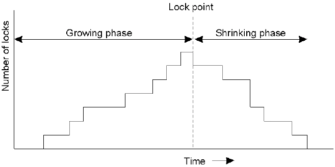
In strict two-phase locking, locks applied during a transaction is held until the transaction has committed or aborted. This solves the problem of dirty writes or premature writes.
Timestamp Ordering
A unique timestamp is assigned to each transaction when it starts. From this, we can get a total ordering of transaction starts, and requests from transactions can be ordered.
Transaction requests are checked immediately:
| Rule | Tc | Ti | |
|---|---|---|---|
| 1 | write | read | Tc must not write an object that has been read by any Ti, where Ti > Tc. This requires that Tc ≥ the maximum read timestamp of the object. |
| 2 | write | write | Tc must not write an object that has been written by any Ti where Ti > Tc. This requires that Tc > the write timestamp of the committed object. |
| 3 | read | write | Tc must not read an object that has been written by any Ti where Ti > Tc. This requires that Tc > the write timestamp of the committed object. |
Replication
Replication of data allows maintenance of copies of data in multiple computers. It provides enhanced performance, high availability and fault-tolerance.
To correctly implement replication, we require replication transparency - the client shouldn't be aware of multiple physical copies of the data and data should be organised as individual logical objects (i.e., operations return one set of values).
Operations on replicated data should be consistent; replicas should report the same data, and some replicas may need to catch-up and process updates.
System Model
Each logical object is implemented by a collection of physical copies turned replicas. For the purpose of the model, we assume an asynchronous system, where the processes fail by crashing, and there are no network partitions.

We can break down a request into five phases:
- A request is made to the front end, which then issues the request directly to the replica manager
- Coordination - the replica managers coordinate to execute the request consistently (decisions need to be made about the relative ordering of requests).
- Execution - replica managers execute requests in such a way that it can be undone
- Agreement - replica managers reach a consensus on the effect of the request that will be committed, and an abort or commit is decided at this stage
- Response - the replica managers respond to the request, via the front end
Group Messages
Management of replicas require multicast communication (i.e., a message sent to just the replica managers, at the same time). Group membership services control multicast by managing the membership of a group (which can be dynamic by servers failing, new ones coming online and other ones going offline). The group membership service provides an interface for membership changes (create/destroy process groups, add/remove prcesses), implements a failure detector (monitors group members for crashes and may suspend potentially failing processes) and monitors reachability of members in the event of a communications crash. The service would also notify group members to membership changes and performs group address expansion.
An application running in a process group must be able to cope with changing membership. The group management service provides each process with a series of views of the membership. Each process in a group holds the same view, and a new view is delivered when a change in membership occurs (to ensure consistency, the group membership protocol holds new views in a queue until all members agree to delivery). New views are delivered at the same time to all processes, and view changes occur in the same order at each process, so processes should always act on the same view in order to maintain consistency. This method is called view delivery.
Another method called view synchronous group communication extends the group delivery to guarantee that a message multicast to members of a view reaches all non-faulty members of the group. This relies on the principles of agreement (all processes deliver the same set of messages in any given view), integrity (a process will deliver a message at most once) and validity (processes always deliver the messages that they send).
In the view-synchronous system, delivery of a new view draws a conceptual line, and every message delivered is either one side of the line or another. You can infer a set of messages delivered to other processes when a new view is delivered.
ISIS implements a synchronous view using TCP/IP, however the main problem is that of ensuring all messages delivered before the next group membership change occurs. A solution to this problem is that messages received by everyone in the group are stable, but when a view change needs to occur, all unstable messages are sent to all, followed by a flush message. When a process has received a flush from all others, a stable state is regained and it can continue.
Fault Tolerance
Fault tolerance attempts to ensure that a correct service is provided, despite failures (so data and functionality is replicated at the replica managers).
The naïve approach is that if one replica is not responding, to try another. Correctness for replicated objects is achieved by linearisability, an interleaved sequence of operations meets the specification of a single correct copy of the object.
The order of operations in the interleaving is consistent with the real times which the operations were requested by the client. The idea is to ensure that replicas are the same as a virtual replica that receives operations in the correct order and doesn't crash. It requires synchronised clocks (which is not always possible). This only applies to operations however, not transaction. Concurrency control is still needed to achieve transaction consistency
One way of implementing fault tolerance is using a passive (primary backup) setup. A single primary replica manager and a number of secondary (backup) replica managers exist, and the frontends communicate with the primary replica manager only. Going back to the five phases of the system model:
- Request - made to the frontend which passes it with a unique identifier to the primary replica manager
- Coordination - FIFO used, in addition with identifier checks to make sure transactions aren't done twice
- Execution - the primary executes the request and stores the response
- Agreement - if the request is an update, the primary pushes the updated state to the backups (which acknowledge)
- Response - primary responds to the frontend which passes back to the client
This is an implementation of linearisability if the primary is correct. It requires a single backup to take over the primary role if the primary fails, and agreement on what operations have taken place at the replicas when the primary fails. View-synchronous communication can be used as the new view can be delivered without the primary, although ordering over the replica managers is required to decide who is to become the new primary. All surviving replicas have received the same operations also.
In active replication, the replica managers play equivalent roles and are organised as a group. Again, we can compare this to the five phases of the system model:
- Request - made to the frontends, including a unique identifier which is multicasted to all the replica managers
- Coordination - group communications system delivers the message to all replica managers in the same order
- Execution - each replica manager executes a request (identically)
- Agreement - is not needed
- Response - each replica manager sends a response to the frontend, which will collect a number of replies and check for consistency
This does not acheive linearisability (the total order in which replica managers process requests is different to the real-time order in which the clients made their requests). However, the weaker condition of sequential consistency is achieved. Replica managers process the same sequence of requests in the same order - happen-before ordering can be used. There is no total ordering over requests (as required by linearisability), just an ordering over requests coming from a specific client.